
Cleaning equipment for pipe fitting

A technology for cleaning equipment and pipe fittings, which is applied in the direction of lighting and heating equipment, dust removal, conveyor objects, etc. It can solve the problems affecting the cleaning effect of quartz tubes and the cleanliness of cleaning tanks, so as to save cleaning liquid, improve loading and unloading efficiency, The effect of reducing the difficulty of operation

Pending Publication Date: 2020-09-29
CHANGZHOU S C EXACT EQUIP
View PDF0 Cites 7 Cited by
  • Summary
  • Abstract
  • Description
  • Claims
  • Application Information

AI Technical Summary

Problems solved by technology

[0002] In the related technology, the rotating mechanism of the quartz tube cleaning machine is immersed in the liquid medicine in the cleaning tank as a whole, and the residue generated by the wear of the transmission parts of the rotating mechanism will affect the cleanliness of the cleaning tank and the cleaning effect on the quartz tube.

Method used


Image

  • Cleaning equipment for pipe fitting
  • Cleaning equipment for pipe fitting
  • Cleaning equipment for pipe fitting

Examples


Embodiment 1

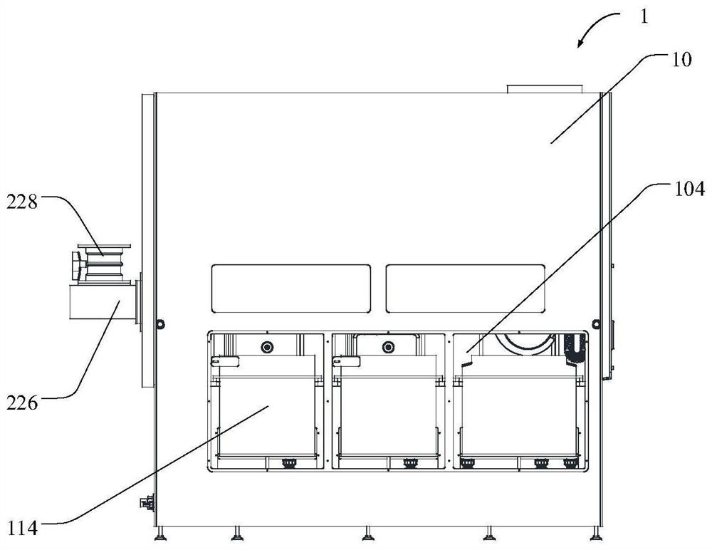
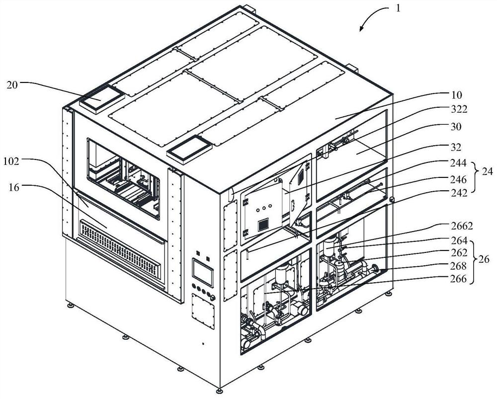
[0051] Such as Figure 1 to Figure 5 As shown, an embodiment of the present invention provides a pipe cleaning device 1 , including: a housing 10 , a mounting plate 110 , and a cleaning tank 114 . Wherein, the housing 10 is provided with a feeding port 102 and a slot opening 104, and the housing 10 is provided with a feeding chamber 106 and a cleaning chamber 108, the feeding port 102 communicates with the feeding chamber 106, and the slot opening 104 is connected with the cleaning chamber 108. The cleaning chamber 108 is connected, and the feeding chamber 106 is located above the cleaning chamber 108 . The mounting plate 110 is connected to the housing 10 , the mounting plate 110 is located in the cleaning cavity 108 , and the cleaning tank 114 can be mounted on the mounting plate 110 .

[0052] The housing 10 of the pipe fitting cleaning device 1 provided in this embodiment is provided with a feeding chamber 106 and a cleaning chamber 108, wherein the pipe fittings to be cl...

Embodiment 2

[0056] Such as Figure 1 to Figure 6 As shown, an embodiment of the present invention provides a pipe cleaning device 1 , including: a housing 10 , a mounting plate 110 , a cleaning tank 114 and an overflow hole 112 . Wherein, the housing 10 is provided with a feeding port 102 and a slot opening 104, and the housing 10 is provided with a feeding chamber 106 and a cleaning chamber 108, the feeding port 102 communicates with the feeding chamber 106, and the slot opening 104 is connected with the cleaning chamber 108. The cleaning chamber 108 is connected, and the feeding chamber 106 is located above the cleaning chamber 108 . The mounting plate 110 is connected to the housing 10 , the mounting plate 110 is located in the cleaning cavity 108 , and the cleaning tank 114 can be mounted on the mounting plate 110 .

[0057] The housing 10 of the pipe fitting cleaning device 1 provided in this embodiment is provided with a feeding chamber 106 and a cleaning chamber 108, wherein the p...

Embodiment 3

[0063] Such as Figure 5 , Figure 7 and Figure 8 As shown, in any of the above embodiments, further, the pipe cleaning equipment 1 further includes: a handling assembly 14 . Wherein, the transport assembly 14 is disposed in the casing 10 and located in the feeding cavity 106 .

[0064] Specifically, the transport assembly 14 includes an installation frame 141 , a lifting frame 143 , a first lifting arm 144 , a second lifting arm 145 , and a hook assembly 146 . The hook assembly 146 specifically includes a hook beam 1462 , a first hook 1464 , a second hook 1466 and a limiting plate 1468 .

[0065] In this embodiment, the feeding chamber 106 in the tube cleaning device 1 is provided with a transport assembly 14 for transporting the tubes to various work stations. Wherein, the installation frame 141 of the transport assembly 14 is connected with the housing 10 , and the lifting frame 143 can slide along the sliding rail 142 on the installation frame 141 , and then transport...


PUM


Abstract

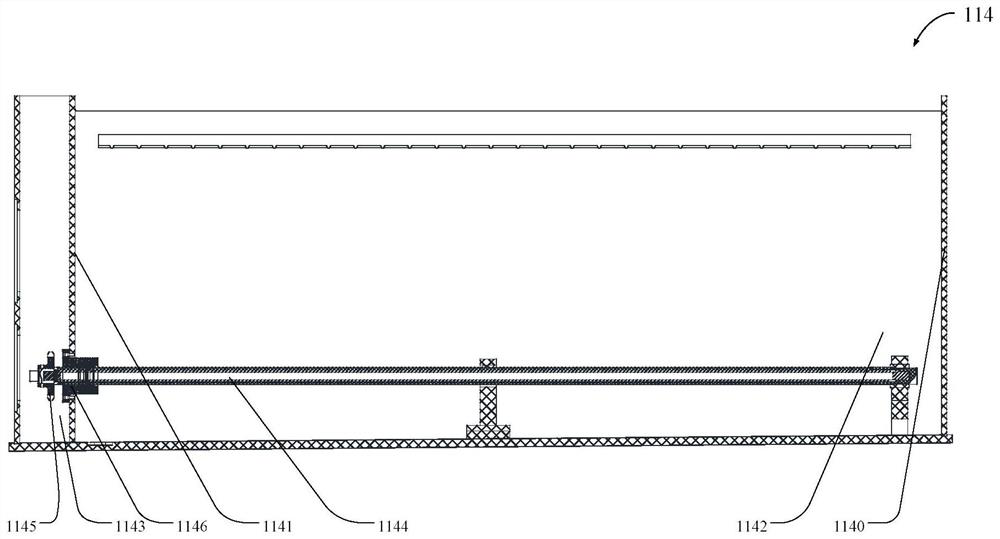
The invention provides cleaning equipment for a pipe fitting. The cleaning equipment for the pipe fitting comprises a shell body, an installation plate and a cleaning groove. A charge port and a groove inlet port are formed in the shell body; a charge cavity and a cleaning cavity are formed in the shell body; the charge cavity is located above the cleaning cavity; the installation plate is connected with the shell body; the installation plate is located in the cleaning cavity; and the cleaning groove is capable of being installed on the installation plate. The cleaning groove specifically comprises a main groove cavity, an auxiliary groove cavity, a rotary element, a transmission element and a sealing element. The main groove cavity is used for placing a cleaning groove; the rotary elementis located in the main groove cavity; one end of the rotary element penetrates through a partition and stretches into the auxiliary groove cavity; the transmission element is located in the auxiliarygroove cavity; and the sealing element is located between the rotary element and the partition. When the transmission element drives the rotary element to rotate, the transmission element does not make contact with the chemical solution in the main groove cavity; and moreover, in the rotating process of the transmission element, the chippings and residues which are generated by the transmission element are intercepted by the sealing element between the rotary element and the partition, so that no pollution to the cleaning solution in the main groove cavity is further ensured, the cleaning effect is improved, and the service life of the cleaning solution is prolonged.

Description

technical field [0001] The invention relates to the technical field of cleaning equipment, in particular to a pipe fitting cleaning equipment. Background technique [0002] In the related art, the rotating mechanism of the quartz tube cleaning machine is immersed in the liquid medicine in the cleaning tank as a whole, and the residue generated by the wear of the transmission parts of the rotating mechanism will affect the cleanliness of the cleaning tank and affect the cleaning effect on the quartz tube. Contents of the invention [0003] The present invention aims to solve at least one of the technical problems existing in the prior art or related art. [0004] To this end, an object of the present invention proposes a pipe cleaning device. [0005] In view of this, the present invention proposes a cleaning device for pipe fittings, comprising: a shell, a feed port and a slot opening are arranged on the shell, a feed chamber and a cleaning chamber are arranged in the hou...

Claims


Application Information

Patent Timeline
Patent Type & Authority Applications(China)
IPC IPC(8): B08B9/023B08B9/027B08B9/032B08B13/00B08B15/02F26B21/00B65G47/90
CPCB08B9/023B08B9/027B08B9/0321B08B9/0325B08B13/00B08B15/02B65G47/90B65G47/901F26B21/004
Inventor 左国军任金枝陈雷申斌成旭李雄朋
Owner CHANGZHOU S C EXACT EQUIP
Learn More