

A device suitable for grinding and chamfering semi-circular aluminum alloy plates
A technology of aluminum alloy plate and chamfering device, which is applied in the direction of machine tools suitable for grinding workpiece edges, grinding drive devices, grinding/polishing safety devices, etc., which can solve the problems of low processing efficiency, hand injury, and installation difficulties, etc. problem, to achieve the effect of grinding precision and improving work efficiency
- Summary
- Abstract
- Description
- Claims
- Application Information
AI Technical Summary
Problems solved by technology
Method used
Image

Examples
Embodiment 1
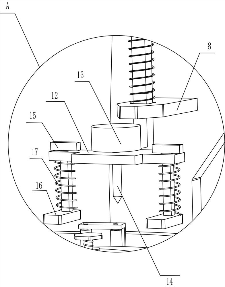
[0023] A device suitable for grinding and chamfering semi-circular aluminum alloy plates, such as Figure 1-3 As shown, it includes a support 1, a rotating shaft 101, a rotating disk 102, a round table 103, a supporting plate 2, a motor 3, a sector gear 4, a rotating shaft 2 5, a transmission gear 6, an eccentric ring 7, a guide plate 8, and a lifting rod 9. Lifting ring 10, spring one 11, machine table 12, motor two 13, chamfering knife 14, telescopic rod one 15, extruding block 16 and spring two 17, the upper side of the front part of the support 1 is rotatably connected with a rotating shaft one 101, the rotating disc 102 is fixedly connected to the upper side of the rotating shaft 101, the round platform 103 is fixedly connected to the top of the rotating shaft 101, the support plate 2 is fixedly connected to the rear side of the upper part of the bearing 1, and the motor 13 is fixedly connected to the upper side of the supporting plate 2, The front side of the output shaf...
Embodiment 2
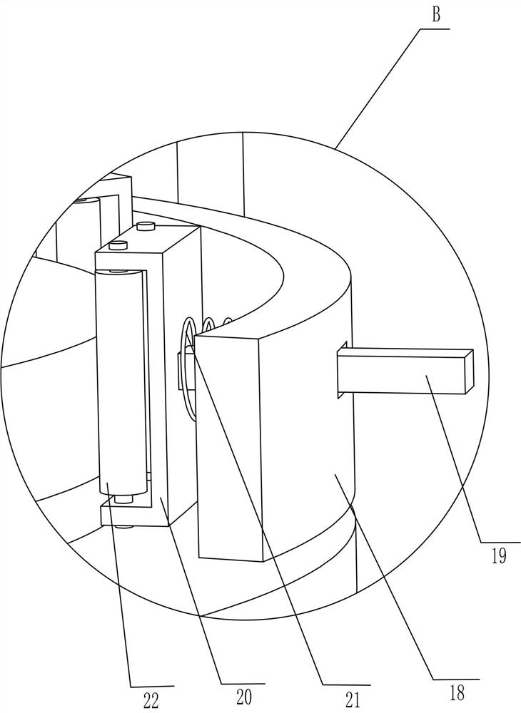
[0026] On the basis of Example 1, such as Figure 4 As shown, it also includes an arc-shaped baffle 18 and a pressing part. The front side of the middle part of the support 1 is fixedly connected with an arc-shaped baffle 18 , and four pressing parts are evenly spaced on the arc-shaped baffle 18 .
[0027] The compression parts include telescopic rod two 19, telescopic frame 20, spring three 21 and rollers 22, and four telescopic rod two 19 are evenly slid on the arc baffle plate 18, and one end of telescopic rod two 19 is fixed near the rotating shaft one 101 A telescopic frame 20 is connected, and a spring three 21 is connected between the telescopic frame 20 and the arc-shaped baffle plate 18. The spring three 21 is sleeved on the telescopic rod two 19, and the upper and lower sides of the telescopic frame 20 are symmetrically connected by a rotating shaft. Roller 22.
[0028] When the semi-circular aluminum alloy plate needs to be compressed, the worker first puts the sem...
Embodiment 3
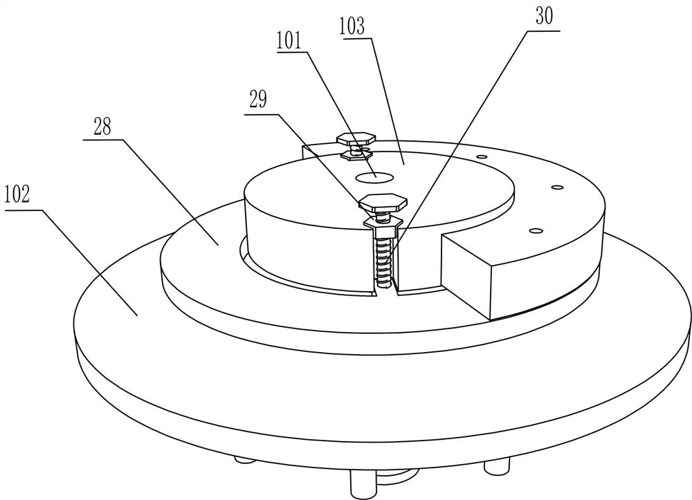
[0030] On the basis of Example 2, such as Figure 5-6Shown, also include bevel gear one 23, rotating shaft three 24, bevel gear two 25, push plate 26 and stir column 27, the front end of motor one 3 output shafts is fixedly connected with bevel gear one 23, the rear portion of bearing 1 The upper side is rotatably connected with rotating shaft 3 24, and the top of rotating shaft 3 24 is fixedly connected with bevel gear 2 25, and bevel gear 2 25 meshes with bevel gear 1 23. There are eight toggle columns 27 uniformly fixedly connected, and the eight toggle columns 27 are distributed in a circular array.
[0031] Also comprise lifting platform 28, nut 29 and screw rod 30, be placed with lifting platform 28 on the rotating disk 102, be connected with nut 29 symmetrically on the round table 103, be equipped with screw rod 30 in the threaded hole of nut 29, the bottom of screw rod 30 It is rotatably connected with the lifting platform 28.
[0032] When the semi-circular aluminum...
PUM
 Abstract
Description
Claims
Application Information