High-pressure pneumatic boosting take-off device for light unmanned aerial vehicle

A high-pressure gas cylinder and machine height technology, applied in the direction of launch/drag transmission, can solve the problems of reducing the range of drones, and achieve the effects of reducing weight, increasing range, and reasonable structural design

Active Publication Date: 2020-09-29
西安宇立航空科技有限公司
View PDF38 Cites 2 Cited by
  • Summary
  • Abstract
  • Description
  • Claims
  • Application Information

AI Technical Summary

Problems solved by technology

[0004] The purpose of the present invention is to solve the existing UAV high-pressure pneumatic booster take-off device in the prior art. After the UAV takes off, the booster device is still located in the UAV. It is relatively heavy, and the UAV needs to overcome the gravity of the booster device to fly when flying, which greatly reduces the problem of the range of the UAV. A light-duty UAV high-pressure pneumatic booster take-off device is proposed, which can After the airframe takes off, the high-pressure gas cylinders and other devices are separated from the airframe by themselves, which greatly reduces the weight of the airframe, improves the flight range of the airframe, and can effectively protect the detached high-pressure gas cylinders to ensure that the high-pressure gas cylinders can continue to be used normally.

Method used


Image

  • High-pressure pneumatic boosting take-off device for light unmanned aerial vehicle
  • High-pressure pneumatic boosting take-off device for light unmanned aerial vehicle
  • High-pressure pneumatic boosting take-off device for light unmanned aerial vehicle

Examples


Embodiment Construction

[0022] The following will clearly and completely describe the technical solutions in the embodiments of the present invention with reference to the accompanying drawings in the embodiments of the present invention. Obviously, the described embodiments are only some, not all, embodiments of the present invention.

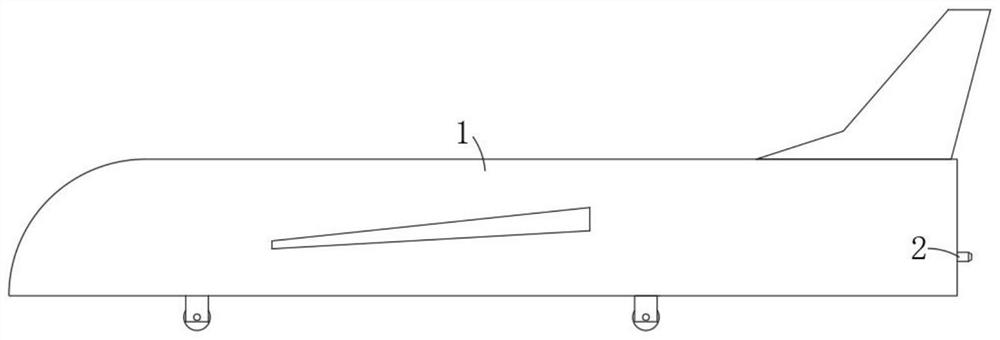
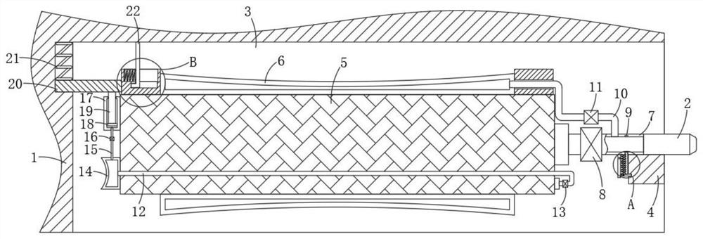
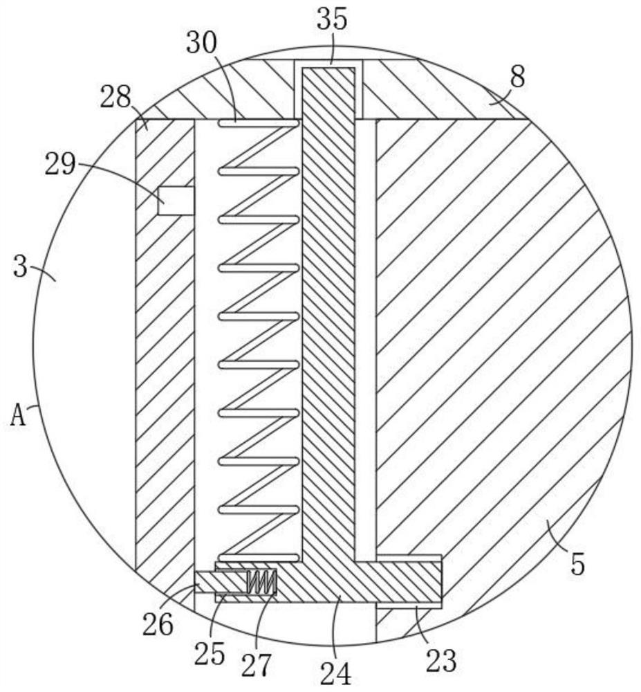
[0023] refer to Figure 1-4 , a light unmanned aerial vehicle high-pressure pneumatic booster take-off device, including a body 1, the bottom of the body 1 is provided with a first installation groove 3, the inner side wall of the first installation groove 3 is fixedly installed with a stopper 4, the first installation groove 3 A high-pressure gas cylinder 5 is slidably connected inside, and the side wall of the high-pressure gas cylinder 5 is provided with a first slide groove 23. There is a first valve 8 on the top, the bottom of the first communication pipe 7 is against the top of the stopper 4, the top of the stopper 4 is fixedly installed with the injection pipe...


PUM


Abstract

The invention discloses a high-pressure pneumatic boosting take-off device for a light unmanned aerial vehicle. The device comprises a machine body; a first mounting groove is formed in the bottom ofthe machine body; a stop block is fixedly mounted on the inner side wall of the first mounting groove; a high-pressure gas cylinder is connected into the first mounting groove in a sliding manner; a first sliding groove is formed in the side wall of the high-pressure gas cylinder; a first communicating pipe communicating with the interior of the high-pressure gas cylinder is fixedly installed on the side wall of the high-pressure gas cylinder; a first valve is arranged on the first communicating pipe; the bottom of the first communicating pipe abuts against the top of the stop block; and an injection pipe is fixedly installed on the top of the stop block. According to the invention, the device is reasonable in structural design; the high-pressure gas cylinder and other devices can be automatically separated from the machine body after the machine body takes off; the weight of the machine body is reduced to a large extent; the voyage of the machine body is increased; the separated high-pressure gas cylinder can be effectively protected; and it is guaranteed that the high-pressure gas cylinder can continue to be normally used.

Description

technical field [0001] The invention relates to the technical field of light unmanned aerial vehicles, in particular to a high-pressure pneumatic booster take-off device for light unmanned aerial vehicles. Background technique [0002] In recent years, UAVs have developed rapidly. The take-off method of light UAVs is mostly booster takeoff. Booster takeoff is generally to install a high-pressure gas cylinder at the tail of the UAV. When the UAV needs to fly, it will The high-pressure gas cylinder is opened, and the gas in the high-pressure gas cylinder is ejected, providing a recoil force to drive the drone to slide. When the drone reaches the take-off speed, the drone can take off. [0003] In the prior art, after the UAV takes off in the existing UAV high-pressure pneumatic booster take-off device, the booster device is still located in the UAV. Since the high-pressure gas cylinder of the booster device is generally relatively heavy, the UAV When flying, it is necessary t...

Claims


Application Information

Patent Timeline
Patent Type & Authority Applications(China)
IPC IPC(8): B64F1/04
CPCB64F1/04
Inventor 谭旭
Owner 西安宇立航空科技有限公司
Why Eureka
Try Eureka