Circulating filtration and sedimentation equipment for water treatment

A circulating filtration and water treatment technology, applied in water/sewage treatment, water/sewage multi-stage treatment, water/sludge/sewage treatment, etc., can solve the problems of clean impurities in water, power consumption, etc., and achieve good treatment The effect of accelerating the binding speed and improving the efficiency of water treatment

Inactive Publication Date: 2020-09-29
盛枫
View PDF0 Cites 2 Cited by
  • Summary
  • Abstract
  • Description
  • Claims
  • Application Information

AI Technical Summary

Problems solved by technology

[0004] The purpose of the present invention is to solve the disadvantages in the prior art that it is difficult to filter the impurities in the water for a single filtration, and it consumes a lot of power to stir the sewage with an electric drive stirring device, and proposes a water treatment circulation filtration sedimentation equipment

Method used


Image

  • Circulating filtration and sedimentation equipment for water treatment
  • Circulating filtration and sedimentation equipment for water treatment
  • Circulating filtration and sedimentation equipment for water treatment

Examples


Embodiment 1

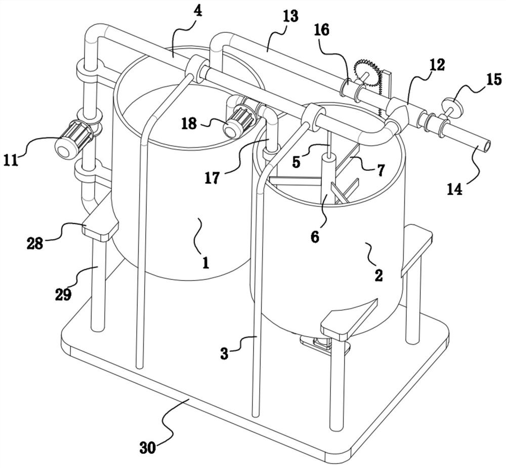
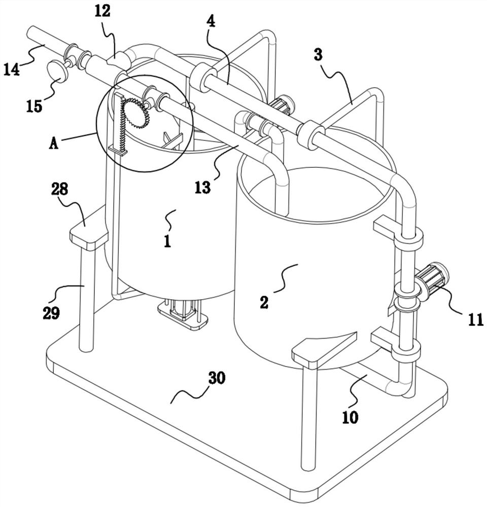
[0023] refer to Figure 1-8 , a kind of circulating filtration sedimentation equipment for water treatment, comprising corresponding settling bucket 1 and filter bucket 2, the outer surfaces of sedimentation bucket 1 and filter bucket 2 are fixed with several fixed blocks 28, and the lower surface of each fixed block 28 is A support leg 29 is fixedly installed, and the bottom ends of the support leg 29 are all fixedly connected on the same workbench 30 .

[0024] The upper surface of the workbench 30 is fixedly equipped with several supporting frames 3 correspondingly arranged, and the first connecting pipe 4 located directly above the sedimentation bucket 1 and the filter bucket 2 is fixedly installed between the supporting frames 3, and the lower pipe of the first connecting pipe 4 The wall is rotatably mounted with a rotating shaft 5 coaxial with the settling barrel 1, the top of the rotating shaft 5 extends upwards into the first connecting pipe 4, and the top of the rotat...

Embodiment 2

[0028] refer to Figure 1-3 , as another preferred embodiment of the present invention, the difference from Embodiment 1 is that the flow diversion mechanism includes a tee 12, a third connecting pipe 13, a fourth connecting pipe 14, a first valve 15, a second valve 16, the first The other end of the connecting pipe 4 is fixedly installed with a tee 12, and the remaining two interfaces of the tee 12 are respectively inserted with a third connecting pipe 13 and a fourth connecting pipe 14, and the outer end of the third connecting pipe 13 is inserted into the filter cartridge 2, A second valve 16 is installed on the third connecting pipe 13 , and a first valve 15 is installed on the fourth connecting pipe 14 . Both the first valve 15 and the second valve 16 are ball valves, and the closing and opening of the valves are controlled by rotating the valves.

[0029] In this embodiment, since the tee 12 is provided, the water flow in the first connecting pipe 4 can be diverted to the...

Embodiment 3

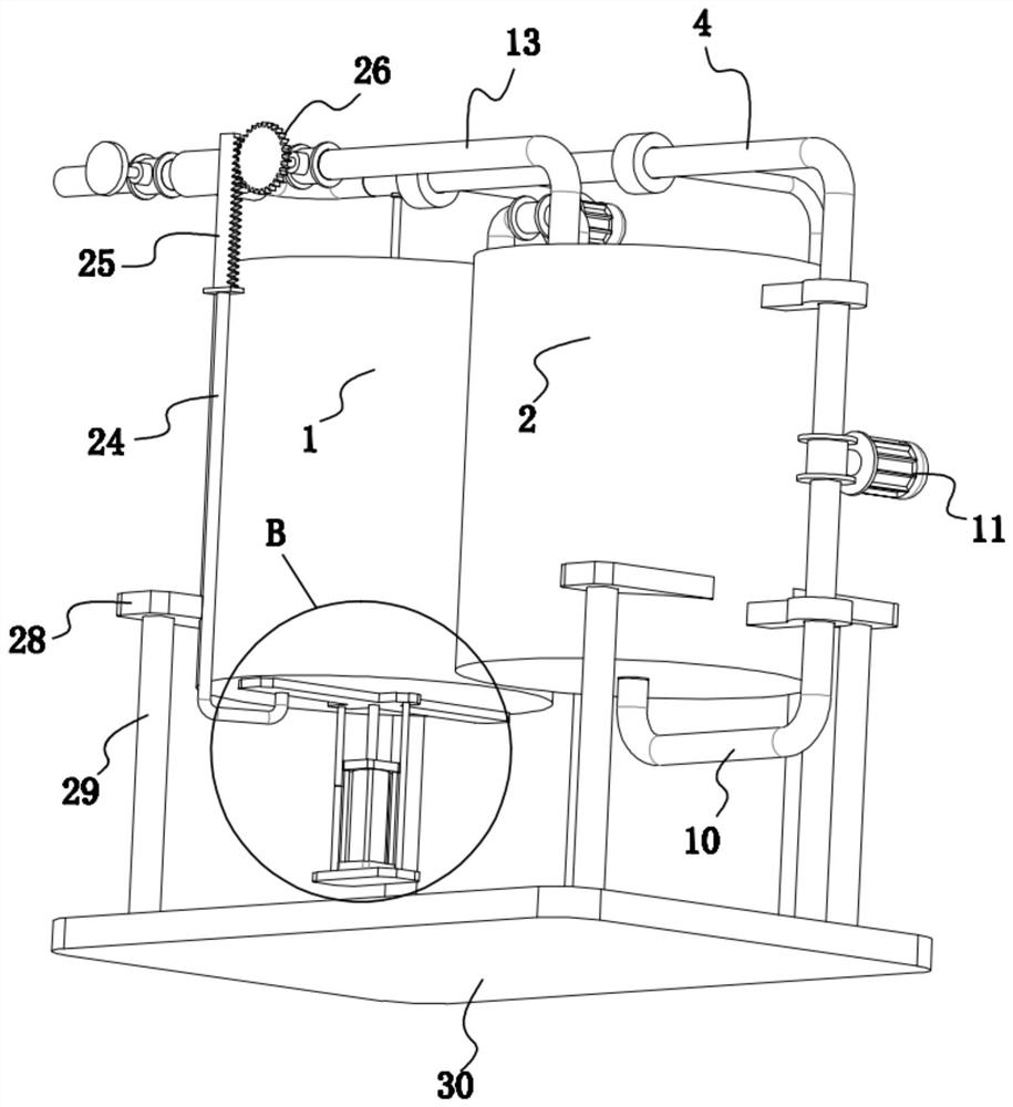
[0031] refer to Figure 4-8 , as another preferred embodiment of the present invention, the difference from Embodiment 2 is that a scraper 8 is fixedly installed at the bottom end of the stirring shaft 6, the lower surface of the scraper 8 is in contact with the bottom surface of the settling bucket 1, and the inner bottom of the settling bucket 1 There is a through groove on the surface, and an insert block 19 is inserted in the through groove. After the bottom end of the insert block 19 extends downwards out of the through groove, a baffle plate 20 is fixedly installed. Two guide rods 21 are arranged on the baffle plate 20. 21 tops are all fixedly connected on the bottom surface of the sedimentation bucket 1, a base plate 22 is fixedly installed between the bottom ends of the two guide rods 21, and a cylinder 23 is fixedly installed on the upper surface of the base plate 22, and the end of the output shaft of the cylinder 23 is fixedly connected to the baffle plate 20 Above,...


PUM


Abstract

The invention relates to the technical field of water treatment equipment, particularly to circulating filtration and sedimentation equipment for water treatment. According to the invention, a rotating shaft which is coaxial with a sedimentation barrel is rotatably mounted on the pipe wall of the lower part of a first connecting pipe; the top end of the rotating shaft extends upwards into the first connecting pipe; a turbine is fixedly mounted at the top end of the rotating shaft; the bottom end of the rotating shaft extends downwards into the sedimentation barrel; a stirring shaft is fixedlymounted at the bottom of the rotating shaft; a plurality of stirring blades are fixedly arranged on a shaft body of the stirring shaft; a second connecting pipe communicating with the interior of a filtering barrel is fixedly installed at the bottom end of the filtering barrel; the tail end of the outer side of the second connecting pipe is fixedly connected to a water inlet of a first water pump;a water outlet of the first water pump is connected with one end of the first connecting pipe; and a diversion mechanism is fixedly installed at the other end of the first connecting pipe. With the equipment, water can be filtered multiple times, and sewage is stirred in a water flow driving mode, so more energy is saved; and meanwhile, impurities in the sedimentation barrel can be automaticallytreated, and more convenience is obtained.

Description

technical field [0001] The invention relates to the technical field of water treatment equipment, in particular to a circulating filtration sedimentation equipment for water treatment. Background technique [0002] In conventional water treatment, filtration generally refers to the process of intercepting suspended impurities in water with granular filter material layers such as quartz sand and anthracite, and the water passes through the filter medium, and the particles are trapped on the surface of the medium or in the medium layer, so that the water is clarified. . The effect of filtration is not only to further reduce the turbidity of the water, but also to remove organic matter, bacteria and even viruses in the water as the turbidity of the water decreases. As for the bacteria and germs remaining in the filtered water, when they lose the protection or attachment of turbidity, they will also be easily killed during the post-filtration disinfection process, which creates...

Claims


Application Information

Patent Timeline
Patent Type & Authority Applications(China)
IPC IPC(8): C02F9/04
CPCC02F1/001C02F1/5281C02F2303/14
Inventor 不公告发明人
Owner 盛枫
Why Eureka
Try Eureka