Carrier rocket previous level recycling system and method and carrier rocket recycling system

A carrier rocket and recovery system technology, applied in the direction of projectiles, self-propelled missiles, offensive equipment, etc., can solve the problem that the upper stage cannot be recovered, and achieve the goal of ensuring internal installation space and payload space, increasing lift, and improving filling efficiency Effect

Pending Publication Date: 2020-09-29
BEIJING XINGJI RONGYAO SPACE TECH CO LTD +1
View PDF6 Cites 4 Cited by
  • Summary
  • Abstract
  • Description
  • Claims
  • Application Information

AI Technical Summary

Problems solved by technology

[0005] Therefore, the technical problem to be solved by the present invention is to overcome the defect in the prior art that the upper stage cannot be recovered during the liquid carrier rocket recovery process, thereby providing a carrier rocket upper stage recovery system and method

Method used


Image

  • Carrier rocket previous level recycling system and method and carrier rocket recycling system
  • Carrier rocket previous level recycling system and method and carrier rocket recycling system
  • Carrier rocket previous level recycling system and method and carrier rocket recycling system

Examples


Embodiment 1

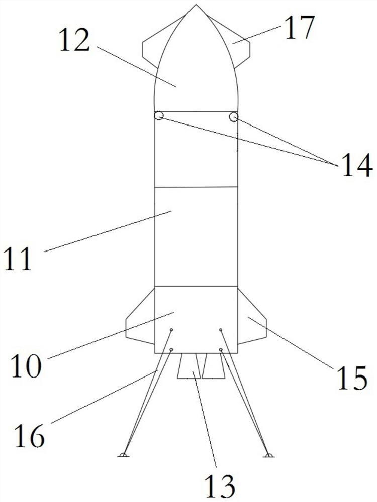
[0046] The upper stage 2 recovery system of the launch vehicle provided by this embodiment, such as figure 1 As shown, it includes: reaction control system, controllable propulsion system, canard 17 and landing support legs; through the reaction control system, the motion attitude of the upper stage is adjusted and controlled to realize de-orbit deceleration of the upper stage; after entering the atmosphere, the upper stage passes The head of the reaction control system and the aerodynamic rudder keep the head facing forward and tilting; the deflection of the aerodynamic control rudder on the canard and tail provides lift to the upper stage, and then adjusts the speed of the descent process; when landing on the ground, Buffering and support are performed by the landing support legs; through the combined use of the above structures, the present invention realizes the recovery of the upper stage 2 of the launch vehicle, and meets the needs of the space launch market such as great...

Embodiment 2

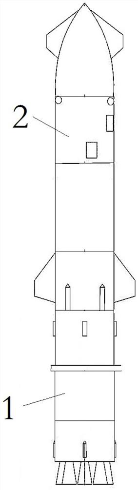
[0054] The recovery system of the launch vehicle provided by this embodiment, such as figure 2 As shown, it includes the booster level 1 recovery system and the upper level 2 recovery system; the upper level 2 recovery system is the same as in embodiment 1. The booster stage 1 recovery system is described in detail below.

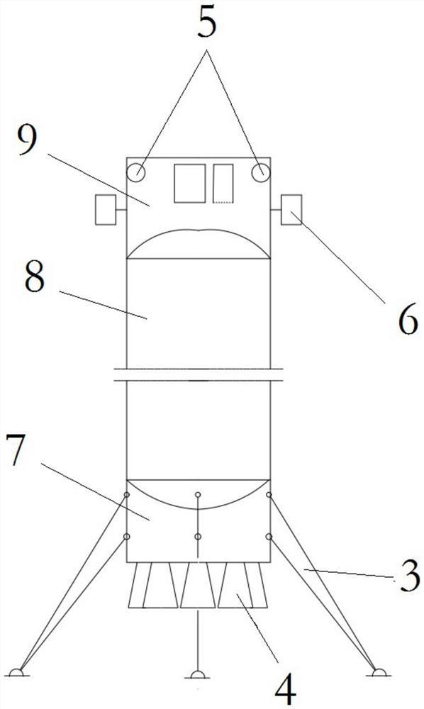
[0055] Such as image 3 As shown, the booster stage 1 is sequentially provided with a first tail section 7, a first storage tank 8 and an interstage section 9 from bottom to top; the lower end of the first tail section 7 is provided with a first controllable propulsion system 4 The rocket motor has a plurality of rocket motors, wherein there are also redundant rocket motors.

[0056] At the same time, the lower end of the first tail section 7 is also provided with a first landing support leg 3; the outer surface of the first tail section 7 is provided with a thermal protection system to prevent the booster stage 1 from being aerodynamically heated and th...


PUM


Abstract

The invention provides a carrier rocket previous level recycling system and method and a carrier rocket recycling system, and belongs to the technical field of carrier rocket recycling. The carrier rocket previous level recycling system comprises a counteraction control system, a controllable propelling system provided with a rocket engine arranged at the tail of a previous level, at least two duck wings symmetrically arranged at the head position of the previous level, at least two tail wings symmetrically arranged at the tail position of the previous level, and landing supporting legs arranged at the tail position of the previous level, wherein the counteraction control system is provided with a plurality of thrusters arranged on the side wall of the previous level, the multiple thrusters are evenly arranged on the side wall circumference, close to the head and tail positions, of the previous level. According to the carrier rocket previous level recycling system, carrier rocket previous level recycling is achieved, the higher carrying capability, the more advanced technology and other space launch market requirements are met.

Description

technical field [0001] The invention relates to the technical field of carrier rocket recovery, in particular to a carrier rocket upper stage recovery system and method, and a carrier rocket recovery system. Background technique [0002] Nowadays, the aerospace industry is developing rapidly, and various technologies for designing rockets have also achieved rapid progress. At present, as the only vehicle for launching satellites into space, reducing the cost of rocket manufacturing and launching is the goal pursued by various companies. [0003] Liquid rockets are composed of an upper stage and a booster stage. At present, the vertical landing and recovery of the booster stage have been realized by using the controllable propulsion deceleration technology. This technology has realized the conventional launch of commercial space launch vehicles and significantly reduced the launch cost. [0004] However, there is no successful precedent for the vertical landing recovery of t...

Claims


Application Information

Patent Timeline
Patent Type & Authority Applications(China)
IPC IPC(8): F42B15/00F42B10/48
CPCF42B15/00F42B10/48
Inventor 彭小波郑立伟施发树
Owner BEIJING XINGJI RONGYAO SPACE TECH CO LTD
Why Eureka
Try Eureka