
Double-layer dynamic battery performance detector

A technology for battery performance and detectors, which is applied to parts, instruments, and measuring electronics of electrical measuring instruments. It can solve problems such as low efficiency and troublesome implementation process, and achieve the goals of improving efficiency, making adjustments convenient and fast, and improving convenience. Effect

Inactive Publication Date: 2020-09-29
CHANGSHA NINGHU MACHINERY CO LTD
View PDF0 Cites 3 Cited by
  • Summary
  • Abstract
  • Description
  • Claims
  • Application Information

AI Technical Summary

Problems solved by technology

[0003] In the existing process of battery detection, dynamic detection methods need to be used, and the core technology of dynamic detection lies in how to detect the dynamic constant when the battery rubs against the brush, that is, by adjusting the angular velocity and linear velocity when the battery rotates To achieve this goal, and the existing device for dynamic detection of the battery needs to be realized through a complex electrical structure to adjust the rotational angular velocity and linear velocity of the battery, and can only detect one group at a time, and requires step-by-step detection, not only The implementation process is cumbersome and inefficient

Method used


Image

  • Double-layer dynamic battery performance detector
  • Double-layer dynamic battery performance detector
  • Double-layer dynamic battery performance detector

Examples

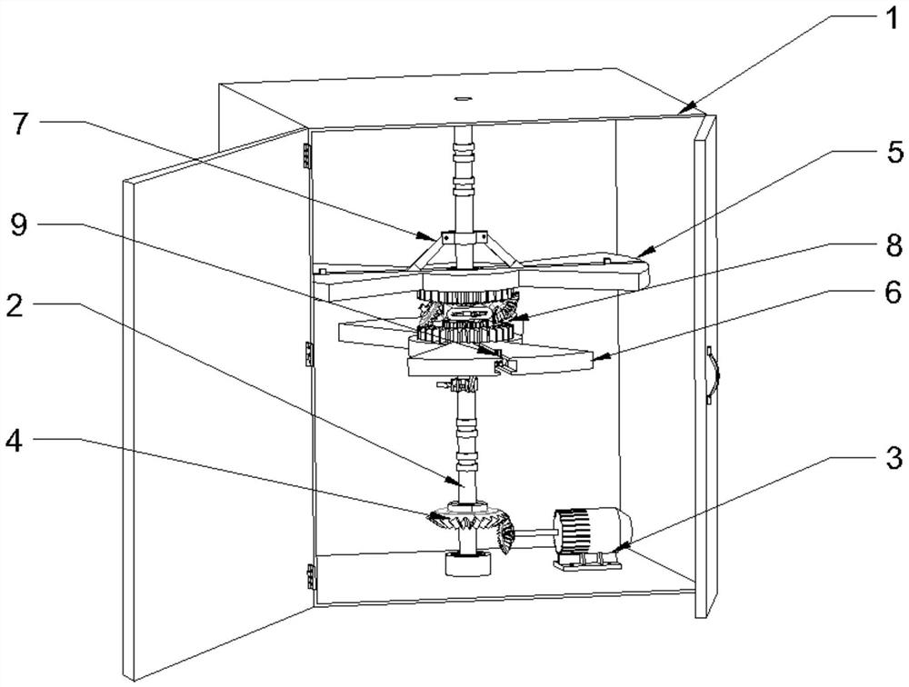
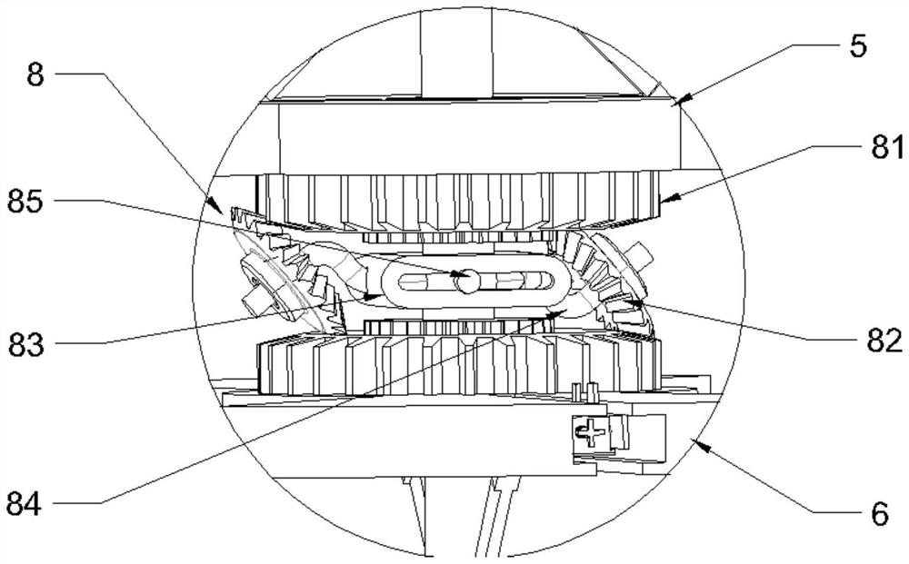
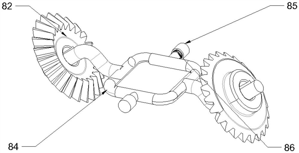

Embodiment Construction

[0024] The present invention will be further described below in conjunction with the accompanying drawings and embodiments.

[0025] Please refer to figure 1 , figure 2 , image 3 , Figure 4 , Figure 5 , Figure 6 and Figure 7 ,in, figure 1 A schematic diagram of the overall structural relationship provided by the present invention; figure 2 A schematic diagram of the structural relationship of the speed regulating mechanism provided by the present invention; image 3 A schematic diagram illustrating the details of the speed regulating mechanism provided by the present invention; Figure 4 A schematic diagram of the internal transmission of the speed regulating mechanism provided by the present invention; Figure 5 A schematic diagram of the partial structure of the adjustment mechanism provided by the present invention; Figure 6 Schematic diagram of the structure of the adjustment mechanism and the clamping part provided by the present invention; Figure 7 It...


PUM


Abstract

The invention provides a double-layer dynamic battery performance detector. The detector comprises an outer cover, a main shaft, a motor, a bevel gear set, an upper turntable, a lower turntable and clamping pieces; the main shaft is inserted into the center of the outer cover; the main shaft is in engaged transmission with the output end of the motor through the bevel gear set at the bottom end; the upper turntable is arranged in the outer cover; the upper turntable is connected with the main shaft through a bearing piece; the lower turntable is fixedly connected to the position, under the upper turntable, of the main shaft; the clamping pieces are symmetrically arranged on the horizontal center line of the upper turntable and the horizontal center line of the lower turntable. A speed adjusting mechanism capable of adjusting the form of the speed adjusting mechanism in a twisting mode is fixedly installed between the upper turntable and the lower turntable. According to the double-layer dynamic battery performance detector provided by the invention, fine adjustment and large-amplitude adjustment structures are ingeniously combined, so that the adjustment requirement can be met at atime, the comprehensive and reasonable battery mounting position adjustment system is formed, and the rotation angular speed of the battery assembly can be adjusted more conveniently and quickly through the speed adjustment mechanism in ingenious meshing transmission.

Description

technical field [0001] The invention relates to the technical field of battery performance detection, in particular to a double-layer dynamic battery performance detector. Background technique [0002] The purpose of battery testing is generally to understand the characteristics of the battery (starting from the battery itself): we need to understand the capacity, internal resistance, voltage characteristics, rate characteristics, temperature characteristics, cycle life, energy density, etc. of the battery through testing. Important parameters, not only need these parameters to demonstrate whether the battery under test has reached the original design goal, but also need to use these parameters to achieve better management and control in the process of using the battery. [0003] In the existing process of battery detection, dynamic detection methods need to be used, and the core technology of dynamic detection lies in how to detect the dynamic constant when the battery rubs...

Claims


Application Information

Patent Timeline
IPC IPC(8): G01R31/385G01R1/04G01R1/02
CPCG01R1/02G01R1/0408G01R31/385
Inventor 不公告发明人
Owner CHANGSHA NINGHU MACHINERY CO LTD
Learn More