
A blind element filling method and system

A filling method and filling system technology, applied in the field of image processing, can solve the problems of large computational load, poor response performance, affecting imaging quality, etc., and achieve the effects of less computational resource occupancy, good consistency, and low computational load.

Active Publication Date: 2021-01-08
北京波谱华光科技有限公司
View PDF10 Cites 0 Cited by
  • Summary
  • Abstract
  • Description
  • Claims
  • Application Information

AI Technical Summary

Problems solved by technology

[0002] Due to the strong dependence of visible light gun sights on light conditions, the observation ability in dark and rainy and fog conditions is poor. The use of infrared sights has become one of the important methods to solve the aforementioned problems.
However, due to the influence of the infrared detector's manufacturing materials and manufacturing process, all the pixels of the infrared detector cannot maintain consistent uniformity, and the pixels with poor response performance or almost no response are called blind pixels during imaging. directly affect image quality
In the infrared sight, the existence of the blind element has a great negative impact on the shooter's judgment, and even leads to misjudgment
One of the existing technical schemes is to perform a sliding window operation after performing a non-uniformity correction operation on the entire image. First, it is judged whether the center point of the sliding window is a blind pixel. Otherwise, the next pixel will be judged; the disadvantage of one of the existing technical solutions is that the full-frame image sliding window strategy is filled with blind pixels, which requires a large amount of calculation, takes up more cloud computing resources, and consumes more time
When the image resolution is high, it may affect the imaging display
The second of the prior art solution is to manually detect the blind cells, mark the position of the blind cells and use 4 adjacent neighborhoods (up, down, left, right, adjacent pixels) or 8 neighborhood pixel values ​​to fill the blind cells; the second of the prior art solutions The disadvantage is that if the blind cells are adjacent to each other and the effective pixel position is occupied by the blind cells, the method is invalid

Method used


Image

  • A blind element filling method and system
  • A blind element filling method and system
  • A blind element filling method and system

Examples


Embodiment Construction

[0045] The principles and features of the present invention are described below in conjunction with the accompanying drawings, and the examples given are only used to explain the present invention, and are not intended to limit the scope of the present invention.

[0046] The infrared gun sight can observe the infrared visual field through the eyepiece to display the living target, and provide the user with the infrared imaging information of the living target under the condition of poor visual conditions. Carry out filling elimination to improve image quality. The present invention combines the technical development status of uncooled infrared detectors applied to infrared gun sights in recent years, and a blind element filling method and system invented based on an infrared gun sight.

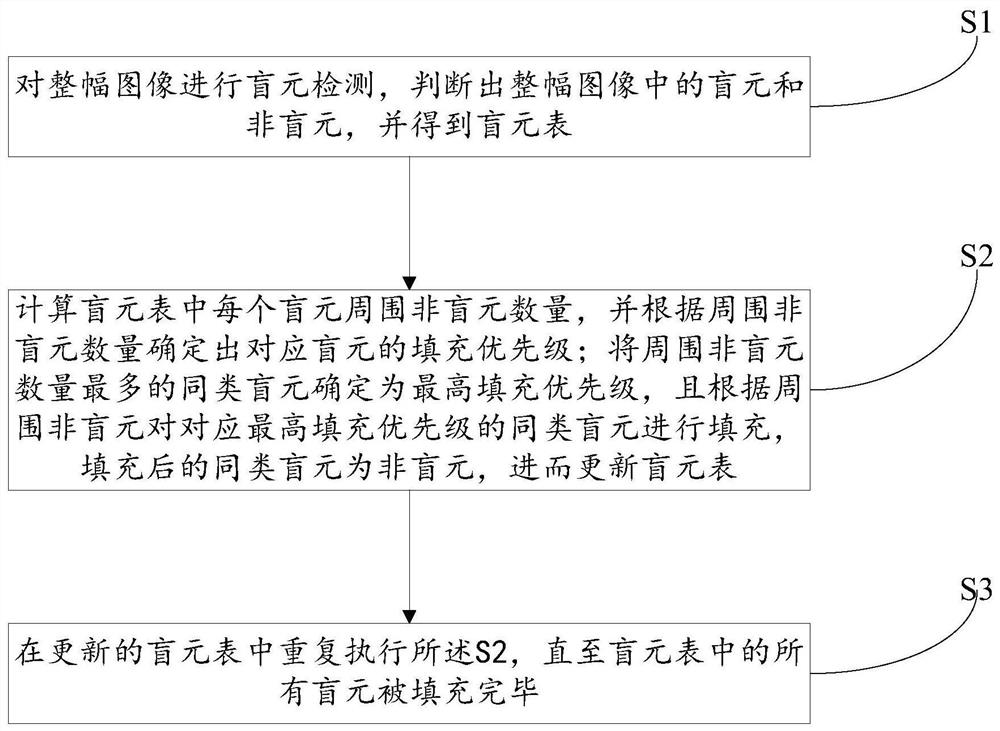
[0047] Such as figure 1 As shown, a blind element filling method includes the following steps,

[0048] S1, perform blind element detection on the entire image, determine blind elements and...


PUM


Abstract

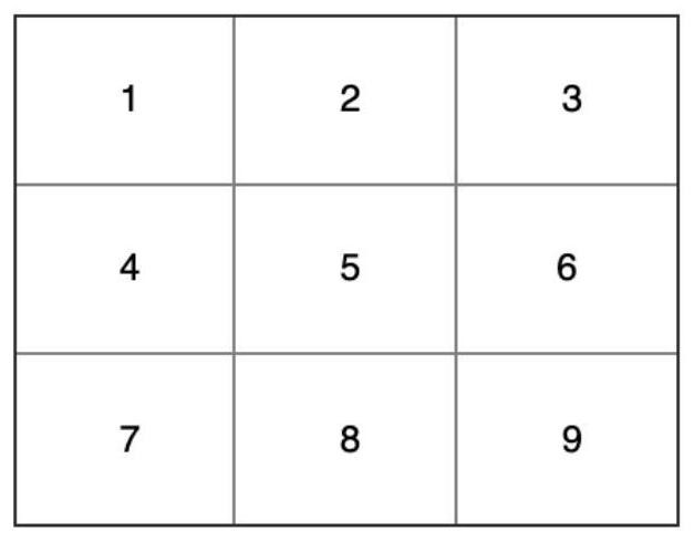
The invention relates to a blind element filling method and system. The method includes the following steps: S1, perform blind element detection on the entire image, determine the blind elements and non-blind elements in the entire image, and obtain a blind element table; S2 , calculate the number of non-blind pixels in the eight adjacent pixels around each blind pixel in the blind pixel table, and determine the filling priority of the corresponding blind pixel based on the number of surrounding non-blind pixels; The blind elements are determined to have the highest filling priority, and the blind elements of the same type corresponding to the highest filling priority are filled according to the surrounding non-blind elements. The filled blind elements of the same kind are non-blind elements, and then the blind element table is updated; S3, in the updated S2 is repeatedly executed in the blind element table until all blind elements in the blind element table are filled. The invention has low computational load, low computing resource occupancy, saves time, and can perform effective filling even when blind elements are adjacently gathered, thereby maintaining the consistency of image response.

Description

technical field [0001] The invention relates to the field of image processing, in particular to a blind element filling method and system. Background technique [0002] Due to the strong dependence of visible light gun sights on light conditions, the observation ability in dark and rainy and fog conditions is poor. The use of infrared sights has become one of the important methods to solve the aforementioned problems. However, due to the influence of the infrared detector's manufacturing materials and manufacturing process, all the pixels of the infrared detector cannot maintain consistent uniformity, and the pixels with poor response performance or almost no response are called blind pixels during imaging. directly affect the image quality. In the infrared sight, the existence of blind elements has a great negative impact on the judgment of the shooter, and even leads to misjudgment. One of the existing technical schemes is to perform a sliding window operation after perf...

Claims


Application Information

Patent Timeline
Patent Type & Authority Patents(China)
IPC IPC(8): G06T5/00G06T7/00G06T7/49G06T7/62
CPCG06T7/0002G06T7/49G06T7/62G06T2207/10048G06T2207/30242G06T5/00
Inventor 祁海军刘智嘉赵金博高旭辉吴金浩刘宏帝
Owner 北京波谱华光科技有限公司
Learn More