Antenna matching circuit
An antenna matching and matching technology, which is applied in the field of wireless communication, can solve the problems of high design difficulty, single signal transmission path, and inability to flexibly adjust antenna matching circuits, etc., so as to increase the number of signal transmission paths, improve utilization rate, increase selectivity and The effect of compatibility
- Summary
- Abstract
- Description
- Claims
- Application Information
AI Technical Summary
Problems solved by technology
Method used
Image
Examples
no. 1 example
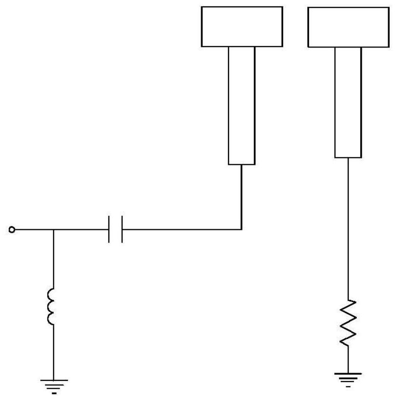
[0026] see Figure 4 As shown, the antenna device of this embodiment includes an antenna (not shown in the figure) and an antenna matching circuit 100, wherein the antenna matching circuit 100 includes a radio frequency port 10, a shrapnel assembly 20, a first matching branch 30 and a compatible test node 40 , the shrapnel assembly 20 includes a signal shrapnel 21, the signal shrapnel 21 is connected to the antenna, the radio frequency port 10 is connected to the signal shrapnel 21 to form a first matching main circuit 50, one end of the first matching branch 30 is connected to the first matching main road 50, and the other end is grounded The compatible test node 40 is disposed at the connection between the first matching branch 30 and the first matching main circuit 50 , and a signal transmission path is formed between the signal shrapnel 21 and the compatible test node 40 .
[0027] Specifically, the first matching main circuit 50 includes a first capacitor C1, the first ca...
no. 2 example
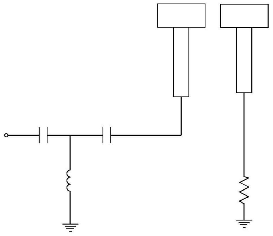
[0030] see Figure 5 As shown, the antenna device of this embodiment includes an antenna (not shown in the figure) and an antenna matching circuit 200, wherein the antenna matching circuit 200 includes a radio frequency port 10, a shrapnel assembly 20, a first matching branch 30a, a first matching branch Road 30b, compatible test node 40a, compatible test node 40b, compatible test node 40c, second matching branch 60, shrapnel assembly 20 includes signal shrapnel 21 and ground shrapnel 22, and signal shrapnel 21 and ground shrapnel 22 are connected to the antenna together. The RF port 10 is connected to the signal shrapnel 21 to form a first matching main circuit 50, one end of the first matching branch 30a is connected to the first matching main circuit 50, and the other end is grounded; one end of the first matching branch 30b is connected to the first matching main circuit 50, and the other end is grounded. The compatibility test node 40a is arranged at the connection betwe...
no. 3 example
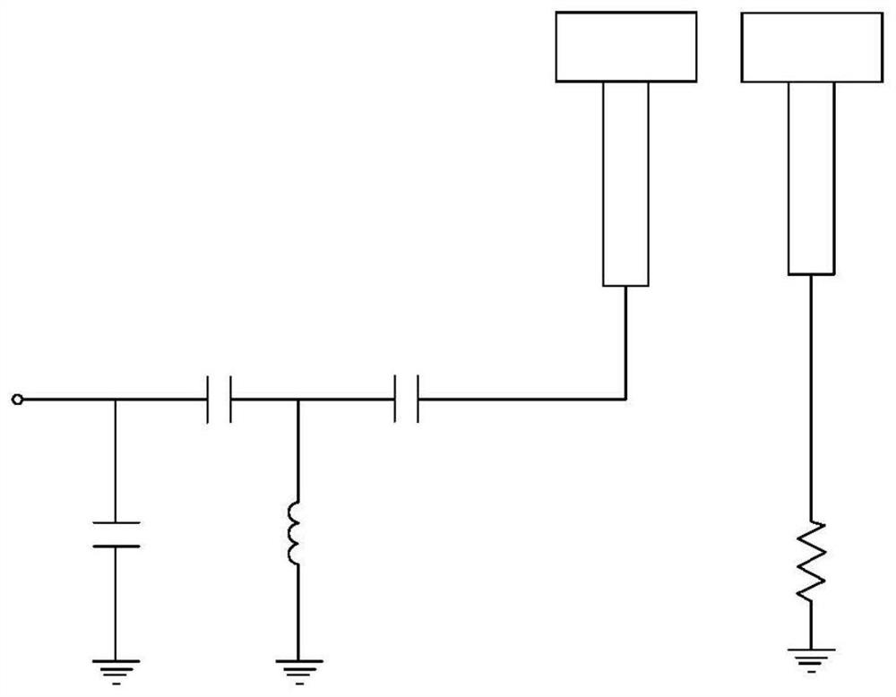
[0036] see Figure 6 As shown, the antenna device of this embodiment includes an antenna (not shown in the figure) and an antenna matching circuit 300, wherein the antenna matching circuit 300 includes a radio frequency port 10, a shrapnel assembly 20, a first matching branch 30a, a first matching branch Road 30b, compatible test node 40a, compatible test node 40b, compatible test node 40c and matching shunt 80, shrapnel assembly 20 includes signal shrapnel 21, ground shrapnel 22a and ground shrapnel 22b, signal shrapnel 21, ground shrapnel 22a and ground shrapnel 22b common antenna. The RF port 10 is connected to the signal shrapnel 21 to form a first matching main circuit 50, one end of the first matching branch 30a is connected to the first matching main circuit 50, and the other end is grounded; one end of the first matching branch 30b is connected to the first matching main circuit 50, and the other end is grounded. The compatibility test node 40a is arranged at the con...
PUM
 Abstract
Description
Claims
Application Information
 - R&D
- Intellectual Property
- Life Sciences
- Materials
- Tech Scout
- Unparalleled Data Quality
- Higher Quality Content
- 60% Fewer Hallucinations
Browse by: Latest US Patents, China's latest patents, Technical Efficacy Thesaurus, Application Domain, Technology Topic, Popular Technical Reports.
© 2025 PatSnap. All rights reserved.Legal|Privacy policy|Modern Slavery Act Transparency Statement|Sitemap|About US| Contact US: help@patsnap.com


