Eureka AIR delivers breakthrough ideas for toughest innovation challenges, trusted by R&D personnel around the world.
Solar cell optical injection feeding and discharging device
What is Al technical title?
Al technical title is built by PatSnap Al team. It summarizes the technical point description of the patent document.
A solar cell and light injection technology, applied in the directions of transportation and packaging, conveyor objects, etc., can solve the problems of missing corners, product scratches, and the mismatch of light injection furnace capacity, so as to ensure safety and improve the speed of feeding. Effect
Pending Publication Date: 2020-10-02
常州易科智能科技有限公司
View PDF0 Cites 0 Cited by
Summary
Abstract
Description
Claims
Application Information
AI Technical Summary
This helps you quickly interpret patents by identifying the three key elements:
Problems solved by technology
Method used
Benefits of technology
Problems solved by technology
[0003] For the light injection furnace installed separately, there is no mature loading and unloading device at present. Manual loading and unloading will easily lead to product defects such as scratches on the product appearance, missing corners, and hidden cracks, resulting in an increase in product failure rate.
[0004] In general, the existing manual loading and unloading device does not match the production capacity of the optical injection furnace, which cannot meet the requirements of rapid production of optical injection, and has the disadvantage of high fragmentation rate, which easily leads to product scratches
Method used
Image
Click on the blue label to locate the original text in one second.
Reading with bidirectional positioning of images and text.
Examples
Embodiment Construction
[0041] The following will clearly and completely describe the technical solutions in the embodiments of the present invention with reference to the accompanying drawings in the embodiments of the present invention. Obviously, the described embodiments are only some, not all, embodiments of the present invention. Based on the embodiments of the present invention, all other embodiments obtained by persons of ordinary skill in the art without creative efforts fall within the protection scope of the present invention.
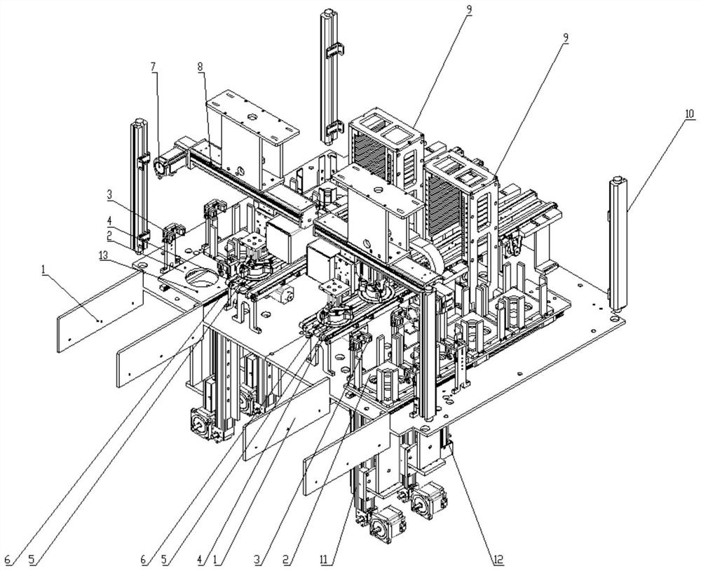
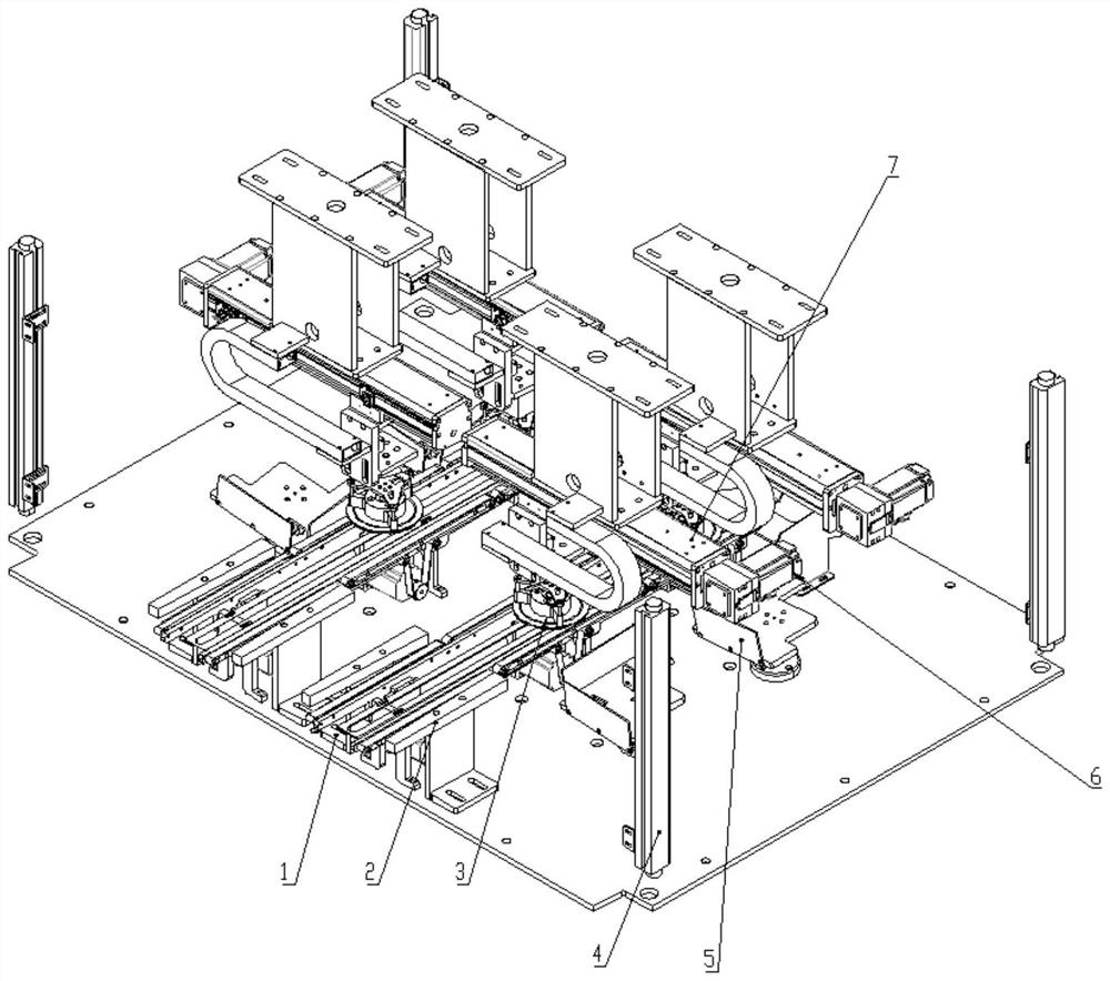
[0042] The invention is a material loading and unloading device for solar cell light injection, including a material loading mechanism and a material unloading mechanism.
[0043] The feeding mechanism includes 1 feeding port, 2 feeding boxes, 3 air knives, 4 transmission tracks, 5 suction cups, 6 cylinders, 7 feeding servo motors, 8 feeding linear modules, 9 buffer boxes, 10 safety gratings, 11 Jacking mechanism, 12 Cache linear module, 13 Feeding platform:
[00...
PUM
Abstract
The invention discloses a solar cell optical injection feeding and discharging device, and relates to the technical field of solar cell production. The solar cell optical injection feeding and discharging device comprises a feeding mechanism and a discharging mechanism; the feeding mechanism comprises a feeding opening 1, a material box 2, an air knife 3, a conveying rail 4, a suction cup 5, a cylinder 6, a feeding servo motor 7, a feeding linear module 8, a temporary storage box 9, a safety optical grating 10, a jacking mechanism 11, a temporary storage linear module 12 and a feeding platform13; and the discharging mechanism comprises a discharging conveying rail 21, a correcting mechanism 22, a suction cup 23, a safety optical grating 24, a discharging box 25, a servo motor 26, a linearmodule 27 and a receiving box 28. By means of an optical injection furnace which can be installed in a matched mode or an independent mode, flexible and soft production can be achieved, rapid operation of an optical injection furnace belt can be adapted, uninterrupted production can be achieved, faults such as double-piece, piece dropping and piece jamming caused by adhesion of cell pieces can beeffectively prevented, continuous operation of the optical injection furnace cannot be affected, and safety of workers can be guaranteed.
Description
technical field [0001] The invention belongs to the technical field of solar cell production, in particular to a solar cell light injection loading and unloading device. Background technique [0002] The light injection process is an important process in battery production. Most of the light injection furnaces are integrated between the sintering and testing and sorting processes, and there is no separate loading and unloading mechanism. The optical injection furnace integrated in the entire production line has certain limitations, the utilization rate is not high, and the production of the normal production line is affected when the finished product is reworked. The light injection furnace installed separately has the advantages of flexibility and convenience, and can be produced at any time, and can also be stopped at any time, which is especially convenient for the production of products that require batch rework. [0003] For the separately installed optical injection f...
Claims
Application Information
Patent Timeline
Application Date:The date an application was filed.
Publication Date:The date a patent or application was officially published.
First Publication Date:The earliest publication date of a patent with the same application number.
Issue Date:Publication date of the patent grant document.
PCT Entry Date:The Entry date of PCT National Phase.
Estimated Expiry Date:The statutory expiry date of a patent right according to the Patent Law, and it is the longest term of protection that the patent right can achieve without the termination of the patent right due to other reasons(Term extension factor has been taken into account ).
Invalid Date:Actual expiry date is based on effective date or publication date of legal transaction data of invalid patent.