Water basin structure and cabinet assembly

The technology of a sink and a sink body is applied in the field of kitchen appliances, which can solve the problems of occupying a countertop operation space, occupying a large space for a water purifier, and a large space occupancy rate for a water purifier, so as to increase the space utilization rate and facilitate arrangement and placement. Effect

Inactive Publication Date: 2020-10-02
FOSHAN SHUNDE MIDEA WASHING APPLIANCES MFG
10 Cites 1 Cited by

AI-Extracted Technical Summary

Problems solved by technology

[0002] At present, during the process of cooking in the kitchen, users gradually increase the requirements for the water quality of the water flowing out of the pool. Most users will choose to install a water purifier on the sink. However, in the prior art, the space occupied by the water purifier Larger, generally, when addi...

Method used

As shown in Figure 1 and Figure 7, on the basis of Embodiment 1, the water tank structure 1 is a single faucet water outlet structure, a joint structure 133 is provided on the second water tank 112, and a pre-filter is also provided 127 and a post-filter 128, wherein the pre-filter 127 can perform preliminary filtration on the fluid flowing into the purification device 12, and the post-filter 128 can filter the ion concentration in the first processing chamber 123 and the second processing chamber 124. The lower one is subjected to secondary filtration before being exported to further improve the water quality of the fluid to meet the water quality needs of users for drinking.
As shown in Figure 2, on the basis of embodiment one, the water tank structure 1 is a double faucet water outlet structure, and a drinking water joint 131 and a water joint 132 are respectively provided on the first water tank 111 and the second water tank 112, in addition A pre-filter 127 and a post-filter 128 are provided, wherein the pre-filter 127 can initially filter the fluid flowing into the purification device 12, and the post-filter 128 can treat the first treatment chamber 123 and the second treatment chamber. The chamber 124 with a lower ion concentration is subjected to secondary filtration before being exported to further improve the water quality of the fluid ...

Abstract

The invention provides a water basin structure and a cabinet assembly. The water basin structure comprises a water basin body, a water purification device and a water outlet device. The water basin body comprises a first water basin and a second water basin, wherein the depth of the first water basin is smaller than that of the second water basin, and the first water basin forms a dislocation space relative to the second water basin in the depth direction. The purification device is arranged in the dislocation space, and one end of the purification device communicates with a water inlet pipe.The water outlet device is arranged on the first water basin and/or the second water basin and communicates with at least part of the purification device. Through the technical scheme, since the spacein a cabinet is limited, the purification device is arranged in the space, which is in shortage relative to the second water basin, of the first water basin, the interior limited space can be sufficiently utilized, meanwhile, the water basin structure is integrally flusher, and bottom space arranging is facilitated.

Application Domain

Technology Topic

Image

  • Water basin structure and cabinet assembly
  • Water basin structure and cabinet assembly
  • Water basin structure and cabinet assembly

Examples

  • Experimental program(4)

Example Embodiment

[0059] Example one
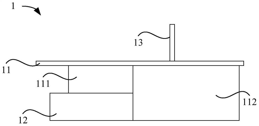
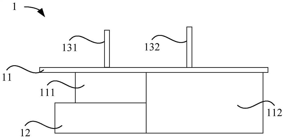
[0060] Such as figure 1 As shown, an embodiment of the present invention provides a water tank structure 1, including a water tank body 11 and a water outlet device 13 provided on the water tank body 11, wherein the water tank body 11 includes a first water tank 111 and a second water tank 111 arranged side by side. Water tank 112, the tank depth of the first water tank 111 is relatively shallow, and the tank depth of the second water tank 112 is relatively deep, and when installed, the notch surfaces of the first water tank 111 and the second water tank 112 are flush, so that the purification device 12 It is arranged in a staggered space where the bottom of the first water tank 111 is higher than the bottom of the second water tank 112.
[0061] Among them, the first water tank 111 is a soaking area, and the second water tank 112 is a cleaning area.
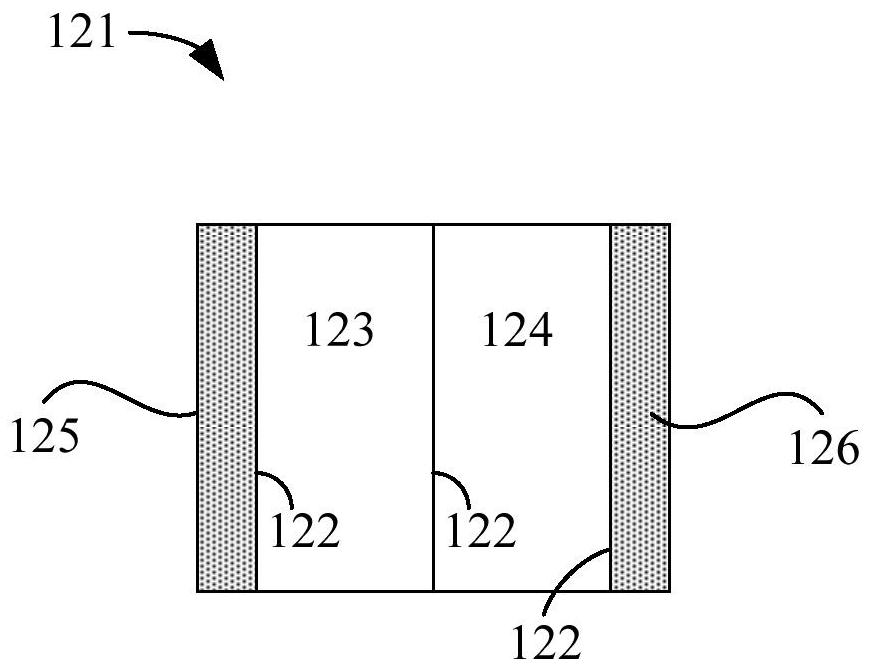
[0062] Further, as image 3 As shown, the purification device 12 includes an electrodialysis membrane stack 121 having a plurality of ion exchange membranes 122. An electrode is provided on both sides of the ion exchange membrane 122. The plurality of ion exchange membranes 122 can form a spaced first treatment. In the chamber 123 and the second processing chamber 124, by arranging two electrodes on both sides of the membrane module structure, an electric field covering the first processing chamber 123 and the second processing chamber 124 can be formed when power is applied. Under the joint action of 122, fluids with different ion concentrations can be formed in the first treatment chamber 123 and the second treatment chamber 124, thereby purifying the water, that is, the fluid flows through the first treatment chamber 123 and the second treatment chamber 124, respectively. At this time, the anions and cations inside the fluid are driven to move under the action of the electric field to achieve the separation effect of concentrated fresh water.
[0063] In a specific embodiment, such as image 3 As shown, three ion exchange membranes 122 are included to form a first processing chamber 123 and a second processing chamber 124. When the left electrode is the first electrode 125 and the right electrode is the second electrode 126, the first processing chamber 123 is located close to the left, and the second processing chamber 124 is located close to the right. From left to right, the three ion exchange membranes 122 are the cation exchange membrane 122, the anion exchange membrane 122 and the cation exchange membrane 122. Normally, the first The electrode 125 is the anode, and the second electrode 126 is the cathode. At this time, the first treatment chamber 123 is a concentrated water chamber, and the second treatment chamber 124 is a fresh water chamber. The water outlet device 13 can be connected to the second treatment chamber 124 for discharge. Fresh water can be cited, and when the polarity is reversed, the polarities of the first electrode 125 and the second electrode 126 are adjusted, that is, the first electrode 125 is the cathode, and the second electrode 126 is the anode. At this time, the first processing chamber 123 is a fresh water chamber, the second treatment chamber 124 is a concentrated water chamber, and the water outlet device 13 is connected with the first treatment chamber 123 to discharge fresh water outward.
[0064] Furthermore, in another embodiment, more ion exchange membranes 122 may be provided, by arranging the first processing chamber 123 and the second processing chamber 124 at intervals, and separating the ions of two adjacent ion exchange membranes 122 The performance is set to the opposite, so that the separation of the concentrated water chamber and the fresh water chamber can be realized, so as to facilitate more fresh water areas to output potable clean water.

Example Embodiment

[0065] Example two
[0066] Such as figure 2 As shown, on the basis of the first embodiment, the water tank structure 1 is a double tap water outlet structure. The first water tank 111 and the second water tank 112 are respectively provided with a drinking water connector 131 and a water connector 132, in addition to a pre-filter 127 and a post-filter 128. The pre-filter 127 can preliminarily filter the fluid flowing into the purification device 12, and the post-filter 128 can compare the ion concentration in the first processing chamber 123 and the second processing chamber 124. The lower one is filtered twice before being exported to further improve the water quality of the fluid to meet the drinking water quality needs of users.
[0067] Among them, such as Figure 4 As shown, the water flowing out through the drinking water connector 131 flows out through the pre-filter element 127, the electrodialysis membrane stack 121, and the post-filter element 128 in sequence. The water quality is relatively high. The user can receive drinking water through the drinking water connector 131, and The water connector 132 is only in communication with the pre-filter 127, so the user can connect the water for general use through the water connector 132, such as for washing kitchen utensils.
[0068] Among them, the pre-filter 127 and the post-filter 128 can be integrated, but the normal flow direction of the pipeline still needs to be ensured.
[0069] In addition, on the side of the first water tank 111 away from the drinking water connector 131, generally the front side, there is a control panel 18 that can display the water output and water quality of the drinking water connector 131 and the water connector 132 in real time, as well as consumables such as the filter element in the purification device 12 In addition, touch buttons can be provided on the control panel 18 to receive control instructions, and then to control the operation of the sink structure 1 to improve the intuitiveness of the control, or the control panel 18 can use a touch screen directly on the screen Display control options.
[0070] Alternatively, the control panel 18 is only used to control the water quality, water temperature, and flow rate of the water discharged through the drinking water connector 131.
[0071] A bubble generating device 16 and an ultrasonic generator 17 are provided on the side of the first water tank 111 close to the drinking water connector 131, that is, on the back side wall, to clean the food or tableware in the first water tank 111.
[0072] In addition, a waterway device 15 communicating with the purification device 12, the water inlet pipe 14, the drinking water connector 131 and the water connector 132 is provided in the gap between the rear side and the rear wall of the water tank structure 1.

Example Embodiment

[0073] Example three
[0074] Such as figure 1 with Figure 7 As shown, on the basis of the first embodiment, the water tank structure 1 is a single tap water outlet structure, and a joint structure 133 is provided on the second water tank 112. In addition, a pre-filter element 127 and a post-filter element 128 are provided. , The pre-filter 127 can preliminarily filter the fluid flowing into the purification device 12, and the post-filter 128 can preliminarily filter the first processing chamber 123 and the second processing chamber 124 with a lower ion concentration before it is exported. Perform secondary filtration to further improve the water quality of the fluid to meet the drinking water quality needs of users.
[0075] Among them, such as Figure 4 As shown, the joint structure 133 can selectively communicate with the rear filter 128 or the pre-filter 127, so that a joint structure 133 can be used to switch between drinking water and daily water, which is more conducive to the overall miniaturization of the sink structure 1.
[0076] Among them, the pre-filter 127 and the post-filter 128 can be integrated, but the normal flow direction of the pipeline still needs to be ensured.
[0077] In addition, a control panel 18 is provided on the front side of the first water tank 111, which can display the water output and water quality of the joint structure 133 in real time, as well as the degree of use of consumables such as filters in the purification device 12. In addition, the control panel 18 can be provided with a touch panel. The control button is used to receive control instructions, thereby controlling the operation of the water tank structure 1 to improve the intuitiveness of the control, or the control panel 18 selects a touch screen to directly display control options on the screen.
[0078] An air bubble generating device 16 and an ultrasonic generator 17 are provided on the rear side wall of the first water tank 111 to clean the food or tableware in the first water tank 111.
[0079] In addition, such as Figure 5 As shown, a waterway device 15 communicating with the purification device 12, the water inlet pipe 14 and the joint structure 133 is provided in the gap between the rear side of the water tank structure 1 and the rear wall.
[0080] On the basis of any of the above embodiments, a baffle plate can be provided between the first water tank 111 and the second water tank 112. In this case, the first water tank 111 and the second water tank 112 can be separately provided with a drain 113 to discharge the corresponding water tank. Water inside.
[0081] On the basis of any of the above embodiments, such as Image 6 As shown, the first water tank 111 and the second water tank 112 are not connected, and a drainage port 113 is provided on the second water tank 112. At this time, due to a certain height difference between the bottom of the first water tank 111 and the second water tank 112, the first The water in the water tank 111 can easily flow to the second water tank 112 and then be discharged through the drain 113.
[0082] In a specific embodiment, a lighting device 19 is provided on the inner wall of the first water tank 111 or the second water tank 112.
[0083] In another specific embodiment, a lighting device 19 is provided on the outer surface of the bottom of the sink body 11.

PUM

no PUM

Description & Claims & Application Information

We can also present the details of the Description, Claims and Application information to help users get a comprehensive understanding of the technical details of the patent, such as background art, summary of invention, brief description of drawings, description of embodiments, and other original content. On the other hand, users can also determine the specific scope of protection of the technology through the list of claims; as well as understand the changes in the life cycle of the technology with the presentation of the patent timeline. Login to view more.

Similar technology patents

Data storage method, data searching method and device

InactiveCN102622434AReduce waste of spaceImprove space utilizationSpecial data processing applicationsEmbedded systemTernary content addressable memory
Owner:HUAWEI DIGITAL TECH (CHENGDU) CO LTD

Automatic mark punching machine

Owner:BAODING GREAT MACHINERY CO LTD

Classification and recommendation of technical efficacy words

  • Easy to arrange
  • Improve space utilization

Industrial truck comprising two load carriages

InactiveUS20110120807A1Easy to arrangeLow loadLifting devicesTruckEngineering
Owner:BT PROD

Liquid pump with axial thrust washer

ActiveUS20130121808A1Simple structural designEasy to arrangePump componentsPumpsAerospace engineeringAxial thrust
Owner:ROBERT BOSCH GMBH

Integrated electric gas turbine

InactiveUS7661271B1Improve space utilizationTurbine/propulsion engine ignitionTurbine/propulsion engine startersAutomotive engineeringGas turbines
Owner:THE UNITED STATES OF AMERICA AS REPRESENTED BY THE SECRETARY OF THE NAVY
Why Eureka
Try Eureka