Eureka AIR delivers breakthrough ideas for toughest innovation challenges, trusted by R&D personnel around the world.

Wire binding device and method of use

A binding device and wire binding technology, applied in towers, building types, buildings, etc., can solve problems such as unsightly craftsmanship, slow binding speed, and wire drawing, and achieve the effects of improving craftsmanship, rapid assembly and disassembly, and stable use.

Active Publication Date: 2020-11-24
LINQU POWER SUPPLY CO OF STATE GRID SHANDONG ELECTRIC POWER CO +1
View PDF8 Cites 2 Cited by
  • Summary
  • Abstract
  • Description
  • Claims
  • Application Information

AI Technical Summary

Problems solved by technology

[0002] In the process of electric power engineering construction and maintenance, it is necessary to use a lot of binding wires for steel strand type pull wires, wire binding wire winding and connection, insulator wire fixing binding, and household wire terminal binding. The long binding wire needs to be coiled, and the manual coiling is relatively slow. When binding manually, the hard binding wire is relatively hard and the winding is not tight.
[0003] At present, when it is necessary to bind the above, it is mainly done manually. The binding speed is slow, the workmanship is not beautiful, and the firmness and reliability are poor. Especially the hard binding wire is relatively hard. Pulling, loosening, falling off, etc.

Method used


Image

  • Wire binding device and method of use
  • Wire binding device and method of use
  • Wire binding device and method of use

Examples


Embodiment Construction

[0030] In order to enable those skilled in the art to better understand the technical solutions in the present application, the technical solutions in the embodiments of the present application will be clearly and completely described below in conjunction with the drawings in the embodiments of the present application. Obviously, the described The embodiments are only some of the embodiments of the present application, but not all of them. Based on the embodiments in this application, all other embodiments obtained by persons of ordinary skill in the art without creative efforts shall fall within the scope of protection of this application.

[0031] Key terms appearing in this application are explained below.

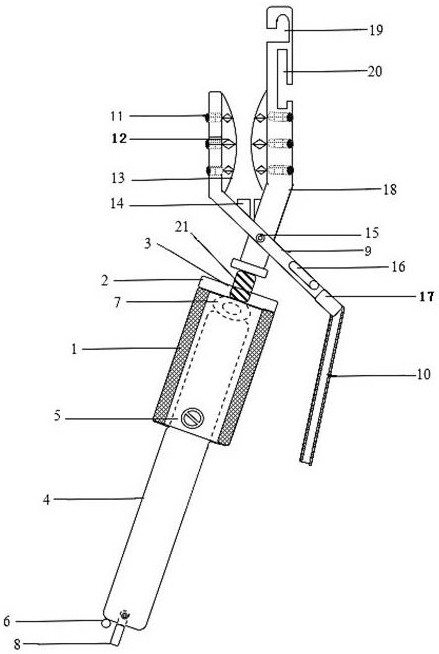
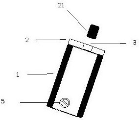
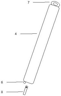
[0032] The wire binding device provided by the application includes a nesting device 1, a rotating shaft 4 and a shearing assembly, the nesting device 1 includes a sleeve and a nesting device cover 2, the sleeve is a hollow cylindrical structure, and the sleeve is in th...


PUM


Abstract

The application provides a binding machine for a binding wire and a usage method. The binding machine comprises a nesting device, a rotating shaft and a shearing component, wherein one end of the rotating shaft is rotationally connected with the nesting device; a positioning member is arranged between the nesting device and the rotating shaft; the shearing component is fixed to one end, which is far away from the rotating shaft, of the nesting device; the shearing component comprises a movable shearing arm and a fixed shearing arm which are rotationally connected; one end of the fixed shearingarm is fixedly connected with the nesting device; the fixed shearing arm is provided with wire collecting holes; the movable shearing arm is provided with a molding element; and a wire cutter is arranged between the movable shearing arm and the fixed shearing arm. Not only can the binding wire be coiled and formed, but also the binding wire can be wound and bound, and the tail end of the bindingwire can be closed up and sheared, and the like. The structure is reasonable; the volume and the size are suitable; the mechanical strength and the hardness meet working use requirements; and the operation efficiency of pulling, binding and winding the wire is improved.

Description

technical field [0001] The application relates to the technical field of electric power engineering construction maintenance, in particular to a wire binding device and a method of use. Background technique [0002] In the process of electric power engineering construction and maintenance, it is necessary to use a lot of binding wires for steel strand type pull wires, wire binding wire winding and connection, insulator wire fixing binding, and household wire terminal binding. The longer binding wire needs to be coiled, and the manual coiling is slower. When binding manually, the hard binding wire is relatively hard and the winding is not tight. [0003] At present, when it is necessary to bind the above, it is mainly done manually. The binding speed is slow, the workmanship is not beautiful, and the firmness and reliability are poor. Especially the hard binding wire is relatively hard. Thread drawing, loosening, falling off and so on. Contents of the invention [0004] A...

Claims


Application Information

Patent Timeline
Patent Type & Authority Patents(China)
IPC IPC(8): E04H12/20
CPCE04H12/20
Inventor 谭焱薛晴艾雪马娥薛鹏胡晓军王利李承鹏王杰王德英张海宁刘彭娟
Owner LINQU POWER SUPPLY CO OF STATE GRID SHANDONG ELECTRIC POWER CO
Why Eureka
Eureka Blog
Learn More