Sliding-vane type pneumatic motor as well as air compressor and internal combustion engine derived from same

An air motor and sliding vane technology, which is applied to internal combustion piston engines, rotary piston engines, rotary piston/oscillating piston pump components, etc., can solve the problems of small crescent air chamber, difficult processing, and large friction, etc. question

Pending Publication Date: 2020-10-02
宋洪涛
View PDF7 Cites 1 Cited by
  • Summary
  • Abstract
  • Description
  • Claims
  • Application Information

AI Technical Summary

Problems solved by technology

The stator of the single-acting sliding vane air motor is cylindrical, and the rotor is cylindrical. There are sliding vane grooves on the rotor, and the sliding vanes are installed in the sliding vane grooves. The rotor is placed eccentrically in the stator, and the stator end covers are blocked at both ends of the stator. , the rotor, stator, and stator end cover together form a crescent-shaped air chamber. The inner surface of the stator of the double-acting slide vane air motor is elliptical or parabolic, which can form two air chambers that are centrally symmetrical. However, such an inner surface of the stator The shape processing is difficult, and the crescent air chamber formed is small, and the economy is poor
When the rotors of the above two kinds of sliding vane air motors rotate, there is a stroke in which the volume of the sealed space gradually decreases. This gas compression stroke does reverse work, resulting in a decrease in engine efficiency.
The two surfaces of the stator end cover and the rotor end surface of the two kinds of sliding vane air motors are in contact with each other, resulting in excessive friction

Method used


Image

  • Sliding-vane type pneumatic motor as well as air compressor and internal combustion engine derived from same
  • Sliding-vane type pneumatic motor as well as air compressor and internal combustion engine derived from same
  • Sliding-vane type pneumatic motor as well as air compressor and internal combustion engine derived from same

Examples


Embodiment Construction

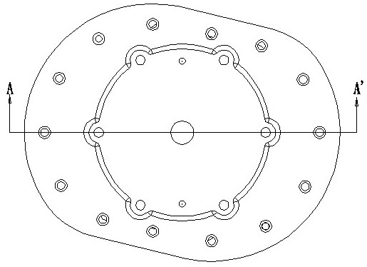
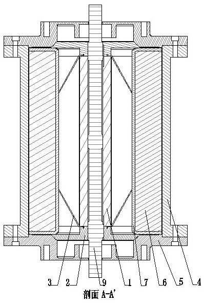
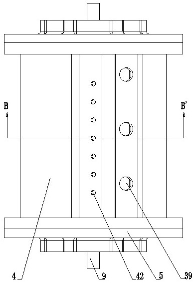
[0069] 1 All components that make up the sliding vane engine are cast, wire cut and machined. The spring leaf (3) is installed in the spring leaf groove (20) of the rotor end cover (2), the rotor end cover (2) is sealed at both ends of the rotor (1), and the slide air-tight strip (7) is sleeved on the slide The lower part and both sides of the sheet (6) form a slide group (71), and the slide group (71) is installed in the slide slot (75), and the above parts are assembled together to form a rotor group (76); the rotor group (76 ) into the cavity of the stator (4), and the stator end caps (5) are sealed at both ends of the stator (4), forming a sliding vane air motor.

[0070] 2. The rotor group (76) of the sliding vane air motor (77) rotates in reverse to form a sliding vane air compressor (78).

[0071] 3. The central axis of the sliding vane air motor (77) is connected together with the central axis of the sliding vane gas compressor (78), and the pressure combustion superc...


PUM


Abstract

The invention relates to a sliding-vane type pneumatic motor as well as an air compressor and an internal combustion engine derived from the same. The sliding-vane type pneumatic motor consists of a rotor, a rotor end cover, a leaf spring, a stator with one or more air chambers, a stator end cover, a sliding vane and a sliding vane airtight strip. A rotor unit of the sliding-vane type pneumatic motor rotates reversely to become a sliding-vane type air compressor. The sliding-vane type pneumatic motor is connected with a middle shaft of the sliding-vane type air compressor to form a body of anengine; and the body is externally additionally provided with a supercharger to form the sliding-vane type internal combustion engine.

Description

technical field [0001] The invention relates to a mechanical engine, in particular to a sliding vane air motor, a sliding vane gas compressor and a sliding vane internal combustion engine. Background technique [0002] Known mechanical motor mainly contains piston engine, turbine engine and sliding vane type air motor now. Piston engines are divided into piston internal combustion engines, piston steam engines and piston compressed gas motors. Due to the reciprocating motion of the piston in the cylinder, the piston engine has the disadvantages of large vibration and low speed. Turbine engines are divided into gas turbines and steam turbines. Due to the need for high-pressure and high-speed gas flow to impact the blades to generate power, turbine engines have strict requirements on manufacturing processes and materials, and many high-temperature and high-pressure gases are directly discharged outside the engine, resulting in serious waste of fuel energy. Now known sliding ...

Claims


Application Information

Patent Timeline
IPC IPC(8): F01C1/344F01C21/10F01C21/08F04C18/344F04C29/00F02B55/14F02B55/02F02B53/04
CPCF01C1/344F01C21/104F01C21/0809F04C18/344F04C29/00F02B55/14F02B55/02F02B53/04F04C2240/20F04C2240/10Y02T10/12
Inventor 宋洪涛
Owner 宋洪涛
Why Eureka
Try Eureka