Heat exchanger

A technology of heat exchangers and heat exchange areas, applied in the direction of heat exchanger types, heat exchanger shells, indirect heat exchangers, etc., can solve the problems of low heat exchange efficiency, deterioration of heat exchange effect, poor heat exchange effect, etc. Achieve the effect of improving heat transfer performance, increasing heat transfer area and flow disturbance, and slowing down the reduction of flow channel cross section

Pending Publication Date: 2020-10-02
浙江高晟光热发电技术研究院有限公司
View PDF0 Cites 8 Cited by
  • Summary
  • Abstract
  • Description
  • Claims
  • Application Information

AI Technical Summary

Problems solved by technology

[0002] Heat exchangers are heat transfer devices often used in the fields of energy, machinery, chemical industry, medicine, food, etc., but the heat exchangers in the prior art have technical problems of low heat exchange efficiency and poor heat exchange effect
Especially in the heat exchanger, the temperature difference between the two working fluids that exchange heat with each other gradually becomes smaller as the heat exchange progresses, which will further lead to the deterioration of the heat exchange effect. Therefore, it is necessary to provide a new heat exchanger to improve the heat exchange efficiency. The heat exchange effect of the heater

Method used


Image

  • Heat exchanger
  • Heat exchanger
  • Heat exchanger

Examples


Embodiment

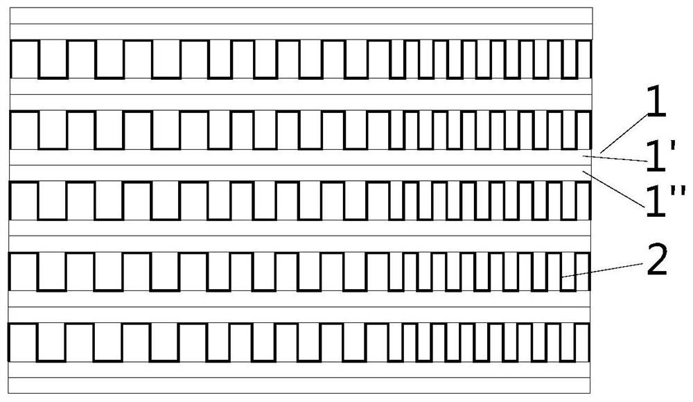
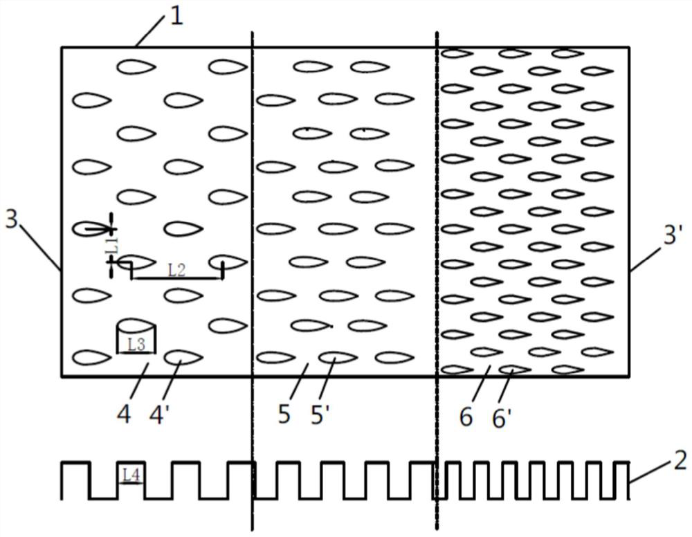
[0041] See Figure 1-Figure 3 , the present embodiment provides a plate-fin air-cooled heat exchanger with variable cross-section microchannels, including:

[0042] Several heat exchange plates (1) on the hot side, several rectangular corrugated fins (2) on the cold side, the heat exchange plates (1) and the rectangular corrugated fins (2) are stacked alternately and connected by diffusion welding. The rectangular corrugated fins (2) of the heat exchanger adopt air as the cooling medium (or called cold-side working medium). The hot-side working fluid may be, for example, carbon dioxide working fluid.

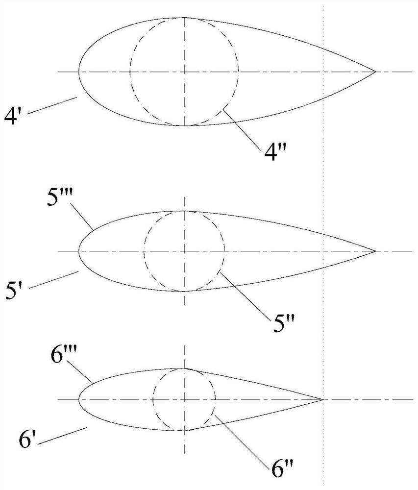
[0043] Wherein, the heat exchange plate (1) is composed of an upper plate (1') and a lower plate (1"), along the flow direction of the working fluid on the hot side, the lower surface of the upper plate (1') and the lower plate (1") The upper surface of the upper surface is sequentially provided with heat exchange plate inlet (3), general heat exchange area (4), level I enhanc...


PUM


Abstract

The invention discloses a heat exchanger. The heat exchanger comprises multiple heat exchange plates and multiple rectangular wavy fins. The multiple heat exchange plates and the multiple rectangularwavy fins are alternately stacked and closely connected. Each heat exchange plate comprises an upper plate and a lower plate. A heat exchange plate inlet, an ordinary heat exchange region, two-stage or higher-stage enhanced heat exchange regions and a heat exchange plate outlet are arranged in the lower surface of each upper plate and the upper surface of the corresponding lower plate in the working medium flowing direction. Multiple discontinuous wing type ribs are arranged in each heat exchange region. Compared with the density of the wing type ribs of each ordinary heat exchange region, thedensity of the wing type ribs of the corresponding first-stage enhanced heat exchange region is increased. Compared with the density of the wing type ribs of each previous-stage heat exchange region,the density of the wing type ribs of the corresponding later-stage enhanced heat exchange region is increased. According to the heat exchanger, each heat exchange plate comprises the multiple corresponding heat exchange regions, different arrangement forms of the wing type ribs are arranged in each heat exchange region, the corresponding rectangular wavy fins are set to be of an unequal-intervalfin structure, the purpose that the heat exchange areas and the flow disturbance of the heat exchange plates and the fins are gradually increased from line to plane in the working medium flowing direction is achieved, and the improvement of the whole heat exchange performance is achieved.

Description

technical field [0001] The invention belongs to the technical field of heat exchangers, in particular to a heat exchanger with variable cross-section microchannels. Background technique [0002] Heat exchangers are frequently used heat transfer devices in the fields of energy, machinery, chemical industry, medicine, food, etc., but the heat exchangers in the prior art have technical problems of low heat exchange efficiency and poor heat exchange effect. Especially in the heat exchanger, the temperature difference between the two working fluids that exchange heat with each other gradually becomes smaller as the heat exchange progresses, which will further lead to the deterioration of the heat exchange effect. Therefore, it is necessary to provide a new heat exchanger to improve the heat exchange efficiency. The heat exchange effect of the heater. Contents of the invention [0003] The present invention provides a heat exchanger with variable cross-section microchannels, su...

Claims


Application Information

Patent Timeline
Patent Type & Authority Applications(China)
IPC IPC(8): F28D9/00F28F3/04F28F3/06F28F9/26
CPCF28D9/0031F28F3/048F28F3/06F28F9/26F28F2275/061
Inventor 朱晓林章晓敏宓霄凌
Owner 浙江高晟光热发电技术研究院有限公司
Why Eureka
Try Eureka