
Array error correction method based on sky wave propagation correction source signals

A technology of array error and sky wave propagation, applied in the field of radar array signal processing, can solve problems such as array error correction

Active Publication Date: 2020-10-02
HARBIN INST OF TECH
View PDF9 Cites 1 Cited by
  • Summary
  • Abstract
  • Description
  • Claims
  • Application Information

AI Technical Summary

Problems solved by technology

[0004] The purpose of the present invention is to solve the problem of array error correction of unknown ionospheric height, and proposes an array error correction method based on sky wave propagation correction source signal

Method used


Image

  • Array error correction method based on sky wave propagation correction source signals
  • Array error correction method based on sky wave propagation correction source signals
  • Array error correction method based on sky wave propagation correction source signals

Examples


Embodiment

[0076] The simulation parameters are set as follows:

[0077] 1. The signal frequency is 6000kHz;

[0078] 2. The number of snapshots is 10000;

[0079] 3. Signal-to-noise ratio SNR=30dB;

[0080] 4. The array adopts a uniform 3×2 area array;

[0081] 5. The ionosphere height is set to 250km;

[0082] 6. The ionospheric height search range is 0-500km, and the search step is 0.1km;

[0083] 7. The phase error of the array element channel is set to change around 60°;

[0084] 8. The amplitude error setting of the array element channel changes around 10 times relative to the reference array element;

[0085] Firstly, through matlab simulation, the search space spectrum of the space azimuth and pitch angle before correction is obtained as follows: Figure 5 Shown; After correction, the search space spectrum for space azimuth and pitch angle is as follows Image 6 Shown, where × represents the true angle of the target.

[0086] Then consider the influence of various errors ...


PUM


Abstract

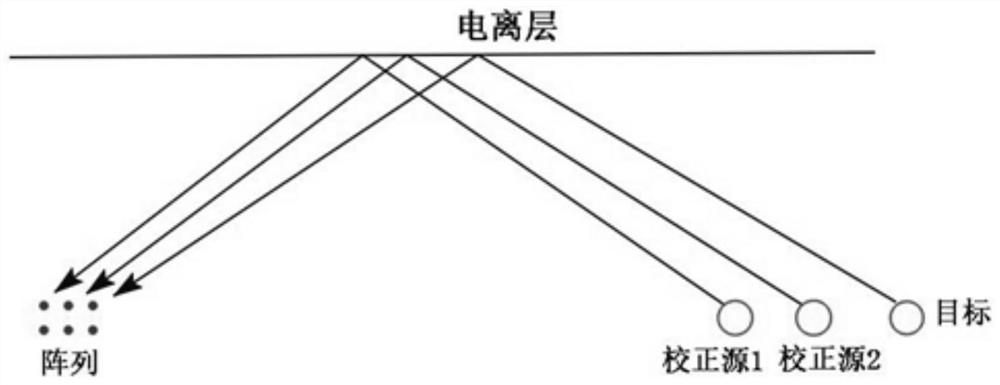
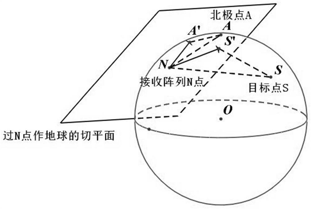
The invention provides an array error correction method based on sky wave propagation correction source signals, and belongs to the technical field of radar array signal processing. The method comprises the steps: arranging two correction sources near a target; utilizing an array error model to construct an equation to solve a pitch angle cosine difference value related to the height of the ionized layer; estimating the height of an ionized layer by using the cosine difference value, calculating pitch angles of two correction sources by using the estimated value of the height of the ionized layer, and finally substituting the pitch angles of the two correction sources into any correction source steering vector to calculate to obtain an estimated value of the amplitude-phase error of the array in the direction, thereby realizing correction of the amplitude-phase error of the array. Based on a model of single-layer ionospheric hypothesis, the correction of array errors is realized by arranging two correction sources near a target, and the influence on a correction result when various errors exist is analyzed.

Description

technical field [0001] The invention belongs to the technical field of radar array signal processing, in particular to an array error correction method based on sky wave propagation correction source signal. Background technique [0002] In the field of radar array signal processing, the main research problem is how to obtain various information of the target by processing the signals received by the radar array. However, while the array is receiving signals, due to the channel amplitude and phase error of the array element itself, that is, the channel gain of each array element is inconsistent, and the array element position error, that is, the position of the array element obtained by tools such as GPS and the real position have deviations, which eventually leads to the target There is a deviation between the actual spatial spectrum and the ideal spatial spectrum, and the correct information of the target cannot be obtained. Therefore, array error correction has always be...

Claims


Application Information

Patent Timeline
IPC IPC(8): G01S7/40G01S7/41
CPCG01S7/4052G01S7/41G01S7/4082
Inventor 毛兴鹏曲祐民
Owner HARBIN INST OF TECH
Learn More