Laser communication terminal transmitting and receiving coaxial real-time calibration method

A technology of laser communication and calibration method, which is applied in the field of laser communication, and can solve problems such as complex composition of the detection system, time-consuming and cumbersome detection process, poor adaptability to the field working environment, etc.

Inactive Publication Date: 2020-10-02
黑龙江瑞霭科技有限公司
View PDF0 Cites 7 Cited by
  • Summary
  • Abstract
  • Description
  • Claims
  • Application Information

AI Technical Summary

Problems solved by technology

[0004] The purpose of the present invention is to solve the problems of the existing equipment for detecting the coaxiality of laser communication terminals. Real-time Calibration Method of Terminal Transceiver Coaxial

Method used


Image

  • Laser communication terminal transmitting and receiving coaxial real-time calibration method
  • Laser communication terminal transmitting and receiving coaxial real-time calibration method
  • Laser communication terminal transmitting and receiving coaxial real-time calibration method

Examples


Embodiment Construction

[0038] The following will clearly and completely describe the technical solutions in the embodiments of the present invention with reference to the accompanying drawings in the embodiments of the present invention. Obviously, the described embodiments are only some, not all, embodiments of the present invention. Based on the embodiments of the present invention, all other embodiments obtained by persons of ordinary skill in the art without creative efforts fall within the protection scope of the present invention.

[0039] It should be noted that, in the case of no conflict, the embodiments of the present invention and the features in the embodiments can be combined with each other.

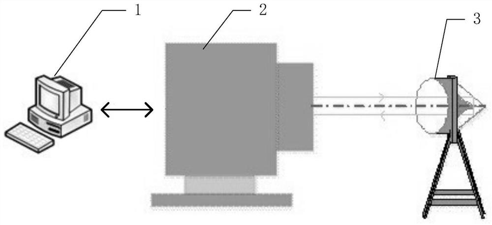
[0040] see figure 1 Describe this embodiment, the laser communication terminal transceiver coaxial real-time calibration method described in this embodiment. Machine 1, laser communication terminal 2 and alignment guide mirror 3 are realized; Said laser communication terminal 2 comprises an opti...


PUM


Abstract

The invention discloses a laser communication terminal transmitting and receiving coaxial real-time calibration method, and belongs to the field of laser communication. The problems that an existing device for detecting the coaxiality of the laser communication terminal is complex in detection system composition, time consuming and tedious in detection process and poor in adaptability to an external field working environment are solved. The calibration method is realized based on an upper computer, a laser communication terminal and a calibration guide mirror. The method is characterized by, through a laser communication terminal, receiving reflected light of signal light and beacon light emitted by the laser communication terminal; analyzing and calculating the light beam angle offset toobtain a transmitting and receiving optical axis deviation angle delta phi; obtaining correction angles delta Fx and delta Fy of a transmitting fine aiming swing mirror in the transmitting optical path according to the transmitting and receiving optical axis deviation angle delta phi, and correcting the current position of the transmitting fine aiming swing mirror in the transmitting optical pathaccording to the delta Fx and delta Fy, thereby realizing calibration of coaxiality of the transmitting optical path and the receiving optical path of the laser communication terminal. The method is mainly used for calibrating the transmitting and receiving coaxiality of the laser communication terminal.

Description

technical field [0001] The invention belongs to the field of laser communication. Background technique [0002] When the existing ground laser communication equipment communicates, the coaxial transmission and reception is a basic requirement. In order to ensure continuous communication between the two terminals, it is necessary to maintain the coaxiality between the optical axes to ensure the consistency and accuracy of the various systems. However, there are many factors that affect the coaxiality of the transmitting and receiving, such as drastic temperature changes and environmental vibrations, which will change the original coaxiality of the transmitting and receiving. While such effects cannot be avoided, since long-distance two-way laser communication requires high pointing accuracy, which is usually measured in μrad, a slight error will cause the laser terminal’s emitting optical axis to be not parallel to the receiving optical axis, and two-way laser communication ...

Claims


Application Information

Patent Timeline
Patent Type & Authority Applications(China)
IPC IPC(8): G02B27/30G02B27/62H04B10/61H04B10/67H04B10/50
CPCG02B27/30G02B27/62H04B10/503H04B10/615H04B10/671
Inventor 于思源李树治李永庄
Owner 黑龙江瑞霭科技有限公司
Why Eureka
Try Eureka