
Traffic flow monitoring device based on remote sensing technology

A technology of monitoring device and remote sensing technology, which is applied in the direction of measuring device, road vehicle traffic control system, traffic control system, etc., can solve the problems of unprepared identification and judgment of traffic flow, insufficient fastening, and inflexible use, etc., to achieve Enhance the effect of mounting and fixing the contact area and fixing tightly

Active Publication Date: 2020-10-02
湖南星图空间信息技术有限公司
View PDF8 Cites 0 Cited by
  • Summary
  • Abstract
  • Description
  • Claims
  • Application Information

AI Technical Summary

Problems solved by technology

[0004] The purpose of the present invention is to provide a vehicle flow monitoring device based on remote sensing technology to solve the problem that the existing vehicle flow monitoring device proposed in the background technology cannot monitor based on remote sensing. It is prone to blurred and unclear situations, unable to prepare for identification and judgment of traffic flow, and the fastness is insufficient when installing with the column, and it is inconvenient to adjust the orientation and angle of the monitoring device, and the use is not flexible enough

Method used


Image

  • Traffic flow monitoring device based on remote sensing technology
  • Traffic flow monitoring device based on remote sensing technology
  • Traffic flow monitoring device based on remote sensing technology

Examples


Embodiment Construction

[0028] The following will clearly and completely describe the technical solutions in the embodiments of the present invention with reference to the accompanying drawings in the embodiments of the present invention. Obviously, the described embodiments are only some, not all, embodiments of the present invention. Based on the embodiments of the present invention, all other embodiments obtained by persons of ordinary skill in the art without making creative efforts belong to the protection scope of the present invention.

[0029] In the description of the present invention, unless otherwise stated, the meaning of "plurality" is two or more; the terms "upper", "lower", "left", "right", "inner", "outer" , "front end", "rear end", "head", "tail", etc. indicate the orientation or positional relationship based on the orientation or positional relationship shown in the drawings, and are only for the convenience of describing the present invention and simplifying the description, rather...


PUM


Abstract

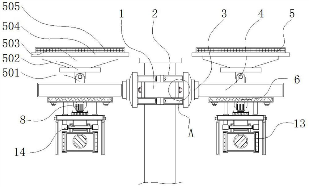
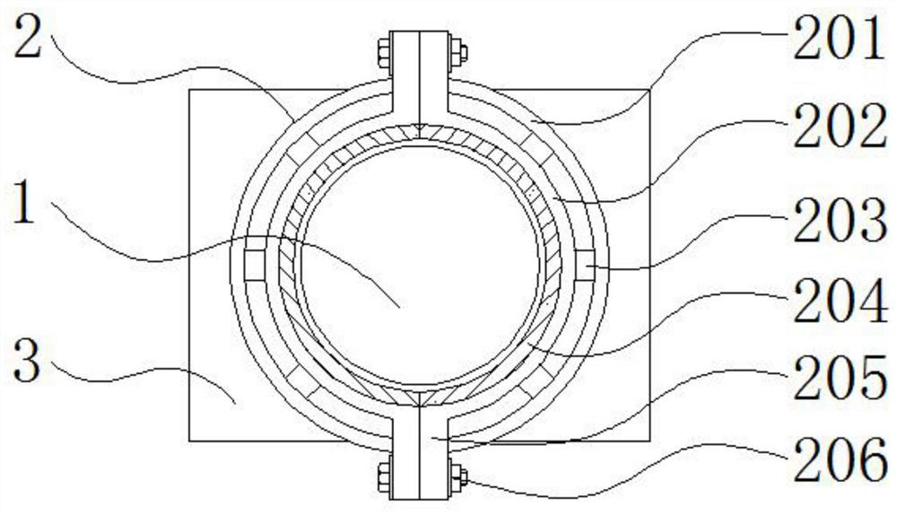
The invention discloses a traffic flow monitoring device based on a remote sensing technology, and relates to the technical field of monitoring devices. The device comprises a strut, a solar mechanismand a remote sensing monitor, wherein a mounting mechanism is arranged on the outer side of the top of the supporting column; a connecting block is welded to one side of the outer part of the mounting mechanism; a supporting plate is fixed to the outer side of the connecting block; and the solar mechanism is installed above the supporting plate, a fixing top plate is installed below the supporting plate through fixing bolts, the fixing bolts penetrate through the two sides of the fixing top plate, an orientation adjusting mechanism is arranged in the middle of the lower portion of the fixingtop plate, and a fixing plate is installed below the orientation adjusting mechanism. The device has the following advantages: electromagnetic waves radiated or reflected by ground objects and the environment can be remotely detected through the remote sensing monitor, the device is a photographic imaging remote sensor, the traffic flow of a road can be monitored on the basis of the remote sensingtechnology, and imaging is achieved through the signal conversion system.

Description

technical field [0001] The invention relates to the technical field of monitoring devices, in particular to a vehicle flow monitoring device based on remote sensing technology. Background technique [0002] Monitoring is one of the most widely used systems in security systems, consisting of a front-end part and a control part. It uses a complete set of monitoring equipment such as cameras, video recorders, monitors, switches, and network cables to form a video system to realize people's monitoring purposes. Remote sensing technology is based on the theory of electromagnetic waves, using various sensing instruments to collect, process, and finally image the electromagnetic wave information radiated and reflected by long-distance targets, so as to detect and identify various scenes on the ground. . [0003] Existing traffic flow monitoring devices cannot monitor based on remote sensing. General surveillance camera devices tend to be blurred and unclear when the traffic flow ...

Claims


Application Information

Patent Timeline
Patent Type & Authority Applications(China)
IPC IPC(8): G08G1/065G01S13/89F16M13/02F16M11/12F16M11/18
CPCG08G1/065G01S13/89F16M13/02F16M11/12F16M11/18
Inventor 张华匡澍张佳栋罗青青游维刘永凡
Owner 湖南星图空间信息技术有限公司
Learn More