Antenna assembly and electronic equipment

An antenna component and antenna technology, applied in the field of communication, can solve the problems of reducing gain, unable to cover, affecting communication effect, etc.

Active Publication Date: 2020-10-02
VIVO MOBILE COMM CO LTD
View PDF17 Cites 7 Cited by
  • Summary
  • Abstract
  • Description
  • Claims
  • Application Information

AI Technical Summary

Problems solved by technology

[0003] The purpose of the embodiment of the present application is to provide an antenna assembly and electronic equipment to solve the problem that the bandwidth of the microstrip patch antenna is relatively narrow, it c

Method used


Image

  • Antenna assembly and electronic equipment
  • Antenna assembly and electronic equipment
  • Antenna assembly and electronic equipment

Examples


Embodiment Construction

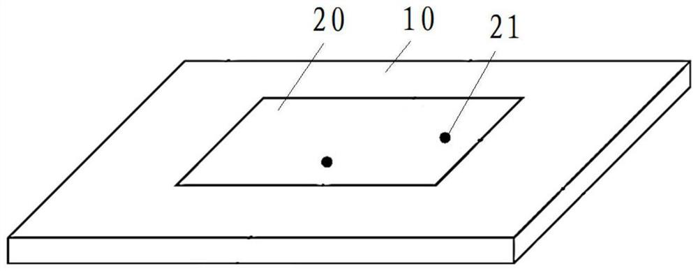
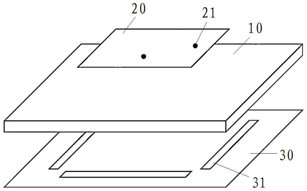
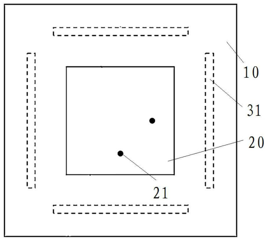
[0038] The following will clearly and completely describe the technical solutions in the embodiments of the present application with reference to the drawings in the embodiments of the present application. Obviously, the described embodiments are part of the embodiments of the present application, not all of them. Based on the embodiments in this application, all other embodiments obtained by persons of ordinary skill in the art without creative efforts fall within the protection scope of this application.

[0039] The terms "first", "second" and the like in the specification and claims of the present application are used to distinguish similar objects, and are not used to describe a specific sequence or sequence. It is to be understood that the data so used are interchangeable under appropriate circumstances such that the embodiments of the application can be practiced in sequences other than those illustrated or described herein. In addition, "and / or" in the specification an...


PUM


Abstract

The invention discloses an antenna assembly and electronic equipment, and belongs to the field of communication. The antenna assembly comprises an antenna dielectric substrate; at least one radiationpatch which is arranged at one side of the antenna dielectric substrate; a first feed structure electrically connected with the radiation patch; and a grounding plate arranged on the other side of theantenna dielectric substrate, wherein the grounding plate is provided with slot units, the projection of each radiation patch on the grounding plate corresponds to at least one slot unit, and the slot units and the projections are arranged at intervals. According to the antenna assembly, resonance can be generated near the resonant frequency of the antenna through the slot units on the groundingplate, so that resonance bandwidth is improved, the overall resonance bandwidth is improved, the equivalent size of the antenna is increased, the bandwidth is wider, radiation coverage can be achievedin the direction opposite to the radiation direction of the antenna, distortion of an antenna radiation pattern is reduced, the gain is enhanced, the antenna efficiency is improved, and the communication effect is improved.

Description

technical field [0001] The application belongs to the communication field, and in particular relates to an antenna assembly and electronic equipment. Background technique [0002] The microstrip patch antenna has the advantages of small size, low profile, light weight, simple manufacturing process, and easy to achieve conformal shape, so it is often used as a millimeter wave antenna. Although the microstrip patch antenna has a simple structure, its bandwidth is relatively narrow, and sometimes it is difficult to cover the required frequency band. The microstrip patch antenna radiates in one direction and cannot cover the direction opposite to the radiation direction; in addition, when the microstrip patch antenna When the ground is larger than several wavelengths, the electromagnetic energy will propagate in the dielectric layer to form surface waves, which will reduce the efficiency of the antenna, and will distort the radiation pattern of the antenna, reduce the gain, and ...

Claims


Application Information

Patent Timeline
IPC IPC(8): H01Q1/48H01Q1/36H01Q1/50H01Q9/04
CPCH01Q1/48H01Q1/50H01Q1/36H01Q9/0407
Inventor 王珅
Owner VIVO MOBILE COMM CO LTD
Why Eureka
Try Eureka