Vehicle-mounted mobile phone wireless charging conversion system and control method
A technology of wireless charging and conversion system, applied in the field of wireless charging, can solve the problem of large power consumption of vehicle-mounted electric frequency, and achieve the effect of ensuring relative stability
- Summary
- Abstract
- Description
- Claims
- Application Information
AI Technical Summary
Problems solved by technology
Method used
Image
Examples
Embodiment 1
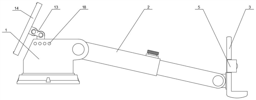
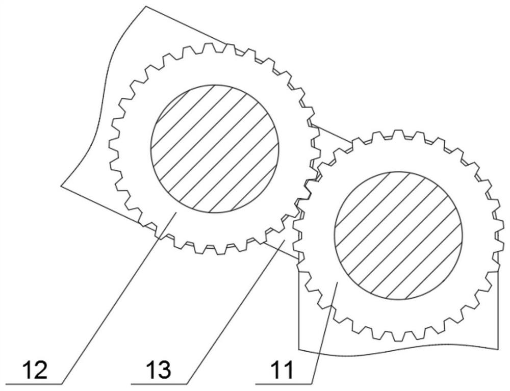
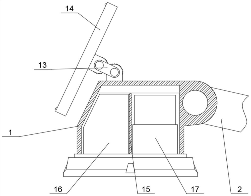
[0034] Embodiment one, with reference to Figure 1-6 , a vehicle-mounted mobile phone wireless charging conversion system and control method, including a mounting base 1, a telescopic frame 2 rotatably connected to the mounting base 1, and a wireless charging frame 3 rotatably connected to the telescopic frame 2, and a solar panel is arranged on the outside of the mounting base 1 14. The upper side of the mounting base 1 is rotatably connected with the first toothed roller 11, and the outer end of the solar panel 14 is rotatably connected with the second toothed roller 12 meshing with the first toothed roller 11. The first toothed roller 11 and the second toothed roller An adapter plate 13 is rotatably connected between the rollers 12, a partition 15 is installed inside the installation seat 1, and a battery 16 is installed inside the installation seat 1 on one side of the partition 15, and the battery 16 is electrically connected to the solar panel 14 , the inside of the moun...
Embodiment 2
[0035] Embodiment two, refer to Figure 6 , the wireless charging conversion system and method are:
[0036] S1: the solar panel 14 converts sunlight energy into electrical energy through the photovoltaic effect;
[0037] S2: the storage battery 16 is responsible for storing the electric current converted by the solar panel 14;
[0038] S3: The frequency converter 17 converts the DC power in the storage battery 16 into AC power and transmits it to the power output coil inside the wireless charging stand 3;
[0039] S4: The power output coil forms an alternating electromagnetic field with the power receiving coil inside the mobile phone;
[0040] S5: The power receiving coil transmits the received AC power to the rectification circuit;
[0041] S6: The rectifier circuit converts the alternating current into direct current to charge the mobile phone battery.
Embodiment 3
[0042] Embodiment three, refer to figure 1 , the outer end of the mounting base 1 is equipped with an indicator light 18 showing the battery 16 power, to help the user remove the power of the battery 16 inside.
PUM
 Abstract
Description
Claims
Application Information
 - R&D
- Intellectual Property
- Life Sciences
- Materials
- Tech Scout
- Unparalleled Data Quality
- Higher Quality Content
- 60% Fewer Hallucinations
Browse by: Latest US Patents, China's latest patents, Technical Efficacy Thesaurus, Application Domain, Technology Topic, Popular Technical Reports.
© 2025 PatSnap. All rights reserved.Legal|Privacy policy|Modern Slavery Act Transparency Statement|Sitemap|About US| Contact US: help@patsnap.com


