
Oil-gas condensing unit with self-defrosting function and oil-gas condensing and recycling method

A condensing unit, oil and gas technology, applied in the direction of vapor condensation, separation methods, chemical instruments and methods, etc., can solve the problems of the continuity of oil and gas condensation, the influence of stability, the decrease of the gas transmission volume of the refrigeration system, and the poor effect of oil and gas condensation, etc. Achieve good defrosting effect, improve refrigeration capacity, and achieve the effect of continuous operation

Pending Publication Date: 2020-10-09
中国人民解放军军事科学院国防工程研究院工程防护研究所
View PDF0 Cites 3 Cited by
  • Summary
  • Abstract
  • Description
  • Claims
  • Application Information

AI Technical Summary

Problems solved by technology

Traditional defrosting methods include hot gas bypass defrosting, electric heat tracing defrosting, and heat pump defrosting. The cooling capacity is insufficient due to the drop, the oil and gas condensation effect is not good, and the hot steam causes a large thermal stress on the heat exchanger and reduces its service life; electric heating defrosting will also cause excessive local thermal stress of the heat exchange tube; heat pump Defrost has a great influence on the continuity and stability of oil and gas condensation

Method used


Image

  • Oil-gas condensing unit with self-defrosting function and oil-gas condensing and recycling method

Examples


Embodiment Construction

[0024] The specific implementation of the present invention will be further described in detail below in conjunction with the accompanying drawings. The accompanying drawings of the present invention are only for exemplary illustrations and cannot be understood as limitations to the present invention. In order to better illustrate the following embodiments, some parts of the accompanying drawings will have The omission, enlargement or reduction does not represent the size of the actual product; for those skilled in the art, it is understandable that some well-known structures and their descriptions in the drawings may be omitted.

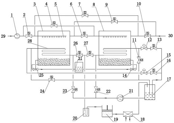
[0025] The connections described in the following embodiments all refer to connections through pipelines, and there is a refrigerant in the condenser 18;

[0026] Such as figure 1As shown, an oil-gas condensing unit with self-defrosting function and an oil-gas condensation recovery method, the oil-gas condensing unit includes an oil-gas compressor 1...


PUM


Abstract

The invention discloses an oil-gas condensing unit with a self-defrosting function and an oil-gas condensing recovery method. The oil-gas condensing unit comprises an oil-gas compressor, two oil condensing chambers / defrosting chambers, a liquid storage tank, a condenser, a refrigeration compressor, a gas-liquid separator, a gear pump, an oil storage tank, an electromagnetic valve and an electronicexpansion valve. The oil-gas compressor is connected with the two oil condensing chambers / defrosting chambers through a first electromagnetic valve and a second electromagnetic valve respectively. According to the oil gas condensation recovery method, an internal and external combined defrosting mode of liquid pipe defrosting and hot gas defrosting is adopted, refrigerant liquid in a liquid storage tank is used for defrosting, and the needed cooling capacity provided by a system is not affected; a frost layer on the surface of a heat exchange coil can be quickly melted through hot air frost blowing, a refrigerant flowing back into the liquid storage tank can also provide a certain degree of supercooling, and the refrigerating capacity is improved. The defrosting effect is better, and thespeed is high; meanwhile, the two oil condensing chambers / defrosting chambers work alternately, and continuous and stable operation of oil gas condensation recovery is achieved.

Description

technical field [0001] The invention belongs to the technical field of oil and gas recovery, and in particular relates to an oil and gas condensing unit with self-defrosting function and an oil and gas condensing recovery method. Background technique [0002] The oil and gas condensing device needs to condense the oil and gas to sub-zero temperature. In many cases, the temperature will be lower, so that the heavy components or high boiling point components (such as water and xylene) in the oil and gas can easily condense on the surface of the heat exchange tube of the condenser to form a frost layer. Defrost treatment is required to maintain the continuous and stable operation of the oil and gas condensing device. Traditional defrosting methods include hot gas bypass defrosting, electric heat tracing defrosting, and heat pump defrosting. The cooling capacity is insufficient due to the drop, the oil and gas condensation effect is not good, and the hot steam causes a large th...

Claims


Application Information

Patent Timeline
Patent Type & Authority Applications(China)
IPC IPC(8): B01D5/00
CPCB01D5/0003B01D5/0039B01D5/0051B01D5/0054B01D5/0075B01D5/009
Inventor 陈叶青薛恒陈经赵强朱新华吕林梅汪剑辉
Owner 中国人民解放军军事科学院国防工程研究院工程防护研究所
Learn More