Cutting path generation method based on greedy algorithm

A technology of cutting path and greedy algorithm, which is applied in the field of mechanical processing, can solve the problems of reducing processing efficiency, processing cutting trajectory with many empty strokes, and the algorithm is not simple, etc., to achieve the effect of improving processing accuracy

Pending Publication Date: 2020-10-09
武汉久同智能科技有限公司
View PDF0 Cites 17 Cited by
  • Summary
  • Abstract
  • Description
  • Claims
  • Application Information

AI Technical Summary

Problems solved by technology

In the prior art, the cutting path algorithm is not simple, resulting in more empty strokes in the proces

Method used


Image

  • Cutting path generation method based on greedy algorithm
  • Cutting path generation method based on greedy algorithm
  • Cutting path generation method based on greedy algorithm

Examples


Embodiment Construction

[0039] The present invention will be further described below in conjunction with accompanying drawing:

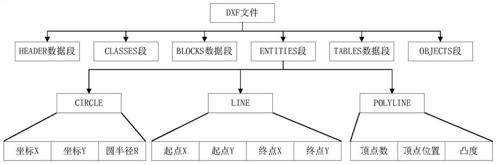
[0040] The workpiece drawing for laser cutting consists of DXF format, such as figure 1 The structure diagram of the workpiece drawing is shown. The workpiece drawing is composed of HEADER data segment, CLASSES data segment, TABLES data segment, BLOCKS data segment, ENTITIES data segment, OBJECTS data segment and file end data segment, and each data segment consists of multiple pairs Group code and group value composition.

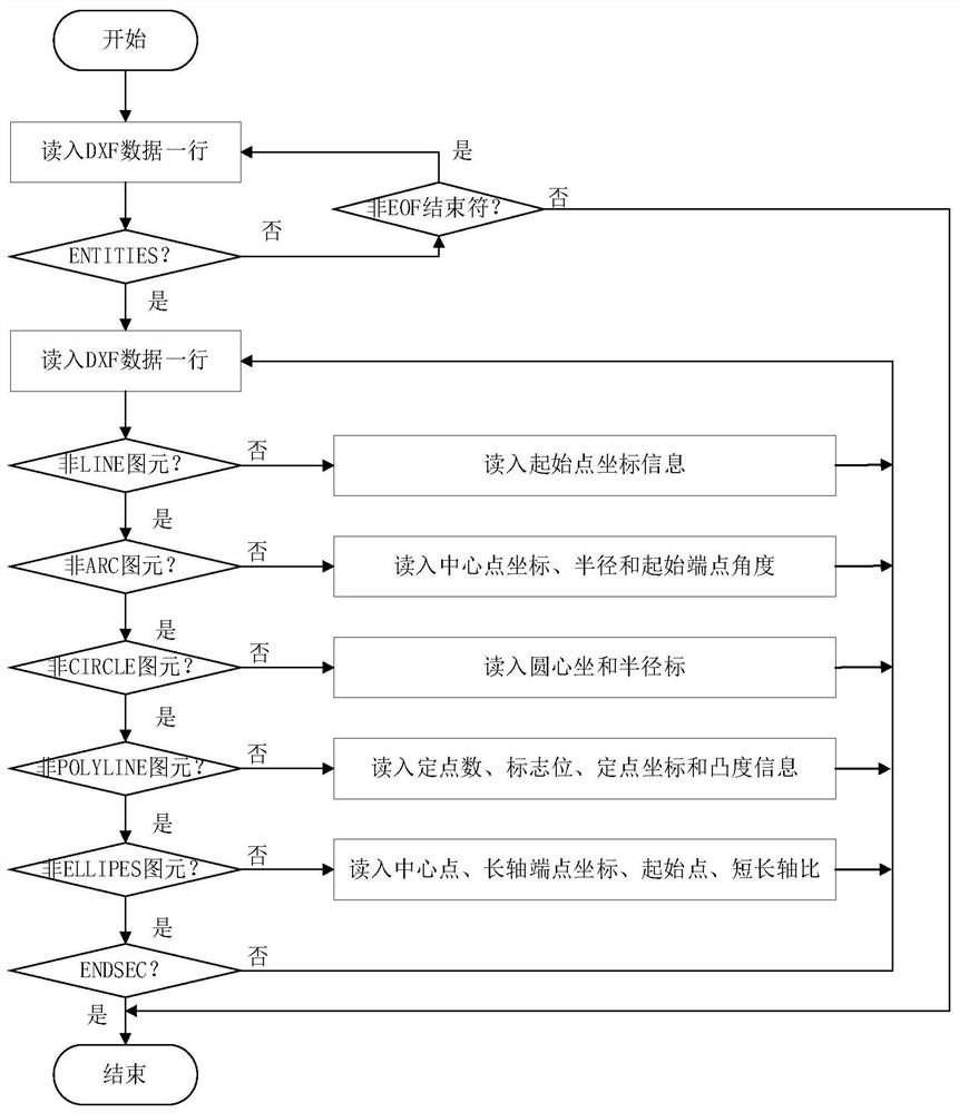
[0041] The content represented by each data segment is different. The main graphic element data in the laser cutting workpiece drawing is in the ENTITIES data segment. This segment is the graphic element data entity segment, which contains all the graphic element information of the laser cutting workpiece drawing, including Types of primitives (lines, arcs, polylines), layer information, line types, colors and other information.

[0042] The key to da...


PUM


Abstract

The invention discloses a cutting path generation method based on a greedy algorithm. A workpiece drawing of laser cutting is composed of a DXF format. The workpiece drawing is composed of an HEADER data segment, a CLASSES data segment, a TABLES data segment, a BLOCKS data segment, an ENTITIES data segment, an OBJECTS data segment and a file end data segment, wherein each data segment is composedof multiple pairs of group codes and group values; according to the automatic programming system, the primitive data of the workpiece drawing can be analyzed, extracted and stored; the method comprises the steps that drawing data are subjected to visual processing, offset processing is conducted on the drawing data according to an offset correction result of the visual processing, a system conducts chain connection on offset primitives, cutting paths are generated one by one, finally, the paths are optimized and sorted based on a greedy algorithm, and a machining cutting track with the shortest idle stroke is generated. The machining precision is improved, and popularization and application value is achieved.

Description

technical field [0001] The invention relates to the technical field of mechanical processing, in particular to a method for generating a cutting path based on a greedy algorithm. Background technique [0002] Usually, the laser cutting of plates does not need to pay attention to the installation and placement of the plates, and directly cuts on the plates to obtain the required workpieces. However, in the laser cutting process of the workpieces in this paper, the biggest difficulty is that the injection molded workpieces have basically been formed. The excess material on the edge of the workpiece is cut, and the injection molded workpiece has a certain degree of plasticity. During the installation of the workpiece, the installation error of the workpiece cannot be avoided, so there are three degrees of freedom deviations in the translation of the workpiece in the XY direction and the rotation in the Z axis direction. The XY axis rotation deviation is positioned by the fixtur...

Claims


Application Information

Patent Timeline
IPC IPC(8): G06F30/12B23K26/38
CPCB23K26/38G06F30/12
Inventor 刘雄王昌杰熊烁周向东宋宝唐小琦
Owner 武汉久同智能科技有限公司
Why Eureka
Try Eureka