Method for welding non-melt-through insulating layer on outer-ring copper foil of transformer

A transformer and insulating layer technology, applied in the manufacture of inductors/transformers/magnets, preventing/reducing unwanted electric/magnetic influences, electrical components, etc., can solve the contact short circuit, detection, and melting insulation of the outer layer copper foil layers and other issues to achieve the effect of solving headaches

Inactive Publication Date: 2020-10-09
AI DE LIGHT DESIGN CO LTD +1
View PDF3 Cites 0 Cited by
  • Summary
  • Abstract
  • Description
  • Claims
  • Application Information

AI Technical Summary

Problems solved by technology

[0002] In the assembly process of the product, some transformers often need to add copper foil to shield the magnetic field and noise on the outermost periphery (outer layer) to avoid electromagnetic interference caused by leakage of the magnetic field and noise. After the peripheral copper foil is wound, in order to facilitate the operation ,The welding position often falls on the top of the product, and then the welding spot is welded manually / semi-automatically / automatically. In fact, these welding methods cannot be completely and accurately controlled, and then the welding point may partially or slightly or severely melt through the insulation layer. , causing the outer copper foil to produce a slight short circuit or a severe short circuit in contact with the internal wire wrap winding of the product
[0003] Such potentially defective products cannot be detected 100% by the existing detection methods, and finally the serious customer complaints of burn-in failure occur after the customer has used it for a period of time

Method used


Image

  • Method for welding non-melt-through insulating layer on outer-ring copper foil of transformer
  • Method for welding non-melt-through insulating layer on outer-ring copper foil of transformer

Examples


Embodiment 1

[0020] In this embodiment, there is no need for deliberate and too precise control during welding, so even if there is a slight melting loss of the insulating adhesive layer (which can be insulating tape or any insulating material) caused by welding, the outer copper foil will never contact The short-circuit phenomenon of close contact with the inner wire wrap winding; the welding method referred to is not limited to soldering iron plus tin, and various other welding methods (such as laser welding) are applicable.

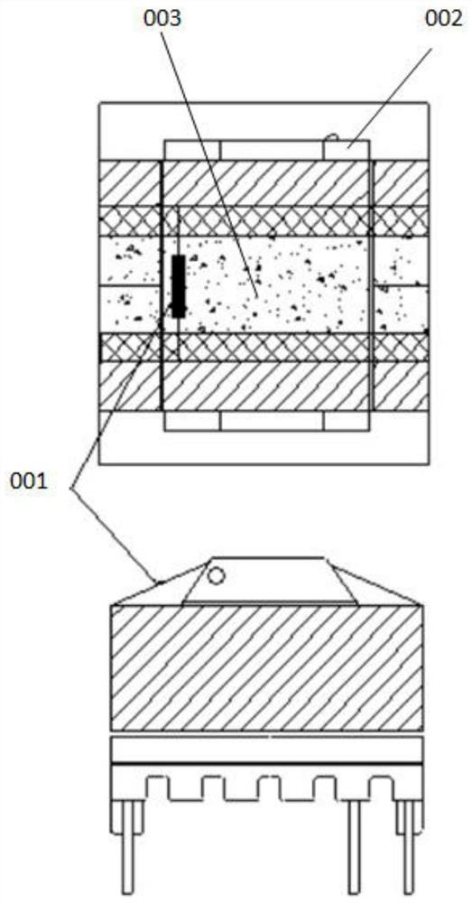
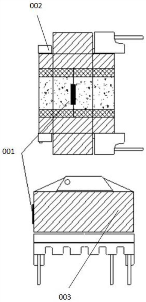
[0021] see Figure 1-Figure 2 As shown, the method for welding the copper foil of the outer ring of the transformer without melting through the insulating layer, the method includes the following steps:

[0022] (1) Set the transformer to be processed, including the magnetic core and wire wrap winding;

[0023] (2) Wind the copper foil on the outermost layer of the magnetic core. When winding, move the joint of the copper foil to the side and leave it on the side ...


PUM


Abstract

The invention discloses a method for welding a non-melt-through insulating layer on a copper foil on an outer ring of a transformer. The method comprises the steps: winding the copper foil on the outermost layer of a magnet core; during winding, enabling the joint of the copper foil to move towards a side edge to be reserved on the side face of the coil winding or the side face of the magnet coreto form a natural space staggered distance; when the joint of the copper foils falls at the position, setting the joint as a welding spot, and then welding the peripheral copper foils; during the winding and welding of a product, moving the relative positions of the welding spots, enabling the welding spots to move towards the side surface of the coil winding or the side surface of the magnet core, forming a natural spatial distance in a manner of spatial placement and relative dislocation, and generating an enough safe distance between a welding spot and a coil, so even if soldering tin meltsthrough an insulating layer due to careless welding, the outer-layer copper foil does not have a short-circuit phenomenon of close-range contact with the inner-layer coil winding.

Description

technical field [0001] The invention relates to the technical field of transformer manufacturing, in particular to a method for welding copper foil on the outer ring of a transformer without melting through an insulating layer. Background technique [0002] In the assembly process of the product, some transformers often need to add copper foil to shield the magnetic field and noise on the outermost periphery (outer layer) to avoid electromagnetic interference caused by leakage of the magnetic field and noise. After the peripheral copper foil is wound, in order to facilitate the operation ,The welding position often falls on the top of the product, and then the welding spot is welded manually / semi-automatically / automatically. In fact, these welding methods cannot be completely and accurately controlled, and then the welding point may partially or slightly or severely melt through the insulation layer. , causing the outer copper foil to produce a slight short circuit or a seve...

Claims


Application Information

Patent Timeline
Patent Type & Authority Applications(China)
IPC IPC(8): H01F41/02H01F27/36
CPCH01F41/02
Inventor 王书斌王子彥白敏吴念慈
Owner AI DE LIGHT DESIGN CO LTD
Why Eureka
Try Eureka