
Shrub ball pruning device for landscaping

A landscaping and pruning device technology, which is applied in the garden field, can solve the problems of dust flying, poor pruning effect, and inability to remove dust, etc., to achieve the effects of improving convenience, ensuring health, and preventing collapse

Inactive Publication Date: 2020-10-13
吴槚婷
View PDF1 Cites 2 Cited by
  • Summary
  • Abstract
  • Description
  • Claims
  • Application Information

AI Technical Summary

Problems solved by technology

[0005] Based on the design structure of the pruning device in the above patent is simple, the effect of pruning is poor, dust removal cannot be carried out during the pruning process, and it is easy to cause the technical problems of flying dust and affecting the surrounding environment. The present invention proposes a shrub ball pruning device for landscaping

Method used


Image

  • Shrub ball pruning device for landscaping
  • Shrub ball pruning device for landscaping
  • Shrub ball pruning device for landscaping

Examples


Embodiment 1

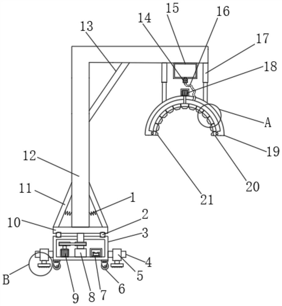
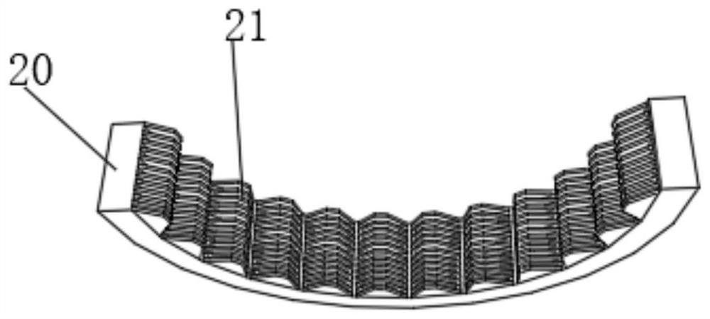
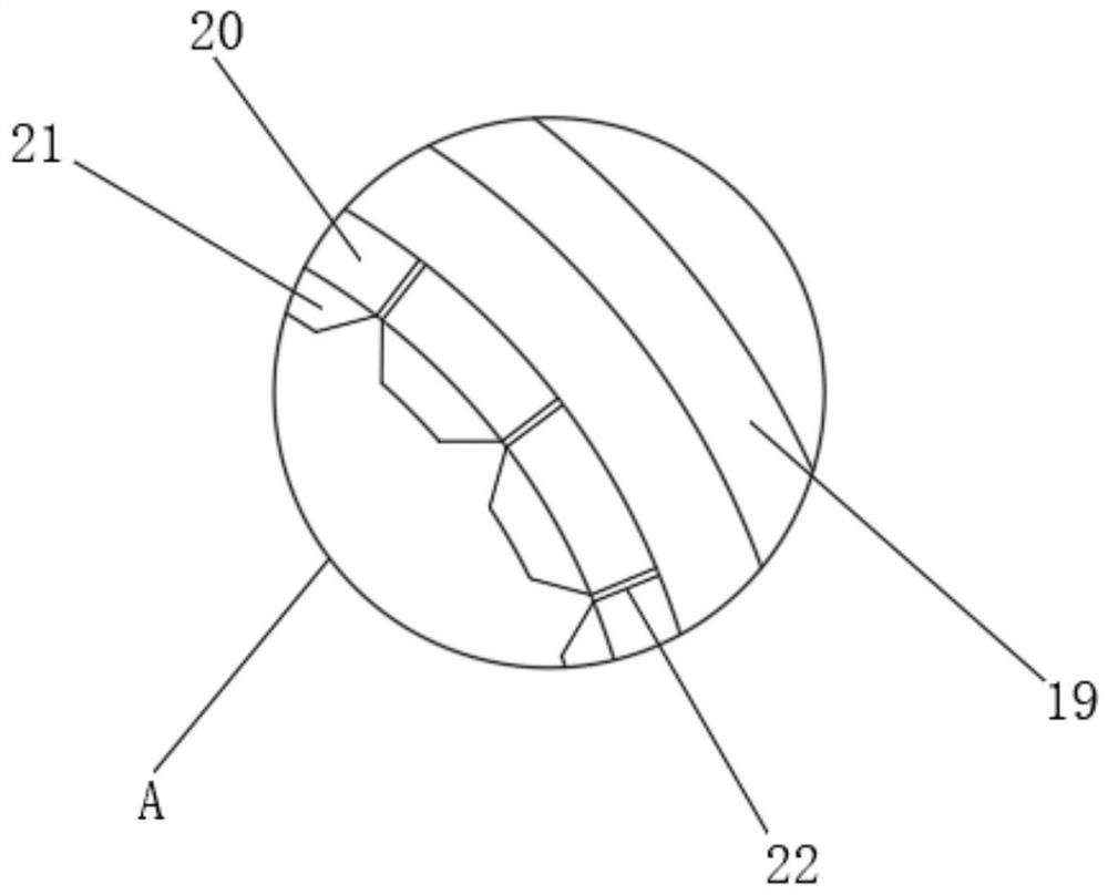
[0030] refer to Figure 1-5 , a shrub ball trimming device for landscaping, comprising an equipment box 3, the inner wall of the bottom of the equipment box 3 is fixed with a bearing seat 8 through a screw, and the inner wall of the bearing seat 8 is connected with a rotating rod through a bearing, and the top end of the rotating rod is sleeved with a The turntable 10, and the top outer wall of the turntable 10 is fixed with a support column 12 of L-shaped structure by screws, and the bottom outer wall of the support column 12 away from the end of the equipment box 3 is fixed with an electric telescopic rod 17 by screws, and one end of the electric telescopic rod 17 piston rod An outer fixed ring 19 is fixed by screws, and the top outer wall of the outer fixed ring 19 is fixed with a motor 18 by screws, and the output shaft of the motor 18 is connected with an inner swivel 20 through a coupling, and the inner wall of the inner swivel 20 is provided with a pruning knife 21, and...

Embodiment 2

[0041] refer to figure 1, a shrub ball pruning device for landscaping. Compared with Embodiment 1, this embodiment also includes that the outer walls on both sides of the equipment box 3 are fixed with mounting plates by screws, and the outer walls of the mounting plates are fixed with hydraulic rods 5 One end of the hydraulic rod 5 piston rod is fixed with a fixed plate 23 by a screw, and the bottom outer wall of the fixed plate 23 is provided with an anti-slip protrusion 24 .

[0042] The piston rod of the hydraulic rod 5 is controlled to elongate, and the fixed plate 23 can contact the ground to fix the device, which improves the stability of the device during work and prevents the device from collapsing.


PUM


Abstract

The invention belongs to the technical field of gardens, particularly relates to a shrub ball pruning device for landscaping, and aims to solve the problems that a pruning device in the patent is simple in design structure and poor in pruning effect, dust cannot be removed in a pruning process, and dust flying is easily caused to influence the surrounding environment. According to the scheme, theshrub ball pruning device comprises equipment box; a bearing seat is fixed to the inner wall of the bottom of the equipment box through screws; a rotating rod is connected to the inner wall of the bearing seat through a bearing; the top end of the rotating rod is sleeved with a rotating disc; a supporting column of an L-shaped structure is fixed to the outer wall of the top of the rotating disc through screws; an electric telescopic rod is fixed to the outer wall of the bottom of the end, away from the equipment box, of the supporting column through screws; and an outer fixed ring is fixed toone end of a piston rod of the electric telescopic rod through screws. According to the shrub ball pruning device, integrated forming of pruning is achieved, and meanwhile, flying dust can be removedin a pruning process, so that pollution of the dust to the garden environment can be reduced, and the body health of people is guaranteed.

Description

technical field [0001] The invention relates to the technical field of gardens, in particular to a shrub ball pruning device for landscaping. Background technique [0002] Garden refers to a specially cultivated natural environment and recreational environment, a beautiful natural environment and recreational environment created by using engineering technology and artistic means in a certain area, by transforming the terrain, planting trees and flowers, building buildings, and arranging garden roads. It's called a garden. It is unique in traditional Chinese architecture and has made great achievements in classical garden architecture. In the process of landscaping, pruning devices are often needed to trim shrub balls. [0003] After searching, the Chinese patent authorization number is CN208210852U, which discloses an arc-shaped shrub pruning device, including a body part, a connecting part and a pruning part; effect and save manpower. [0004] The pruning device in the a...

Claims


Application Information

Patent Timeline
Patent Type & Authority Applications(China)
IPC IPC(8): A01G3/04B08B15/04
CPCA01G3/0435B08B15/04
Inventor 吴槚婷
Owner 吴槚婷
Learn More