Pipe internally inlaid with welding flux and welding technology

A welding process and pipe fitting technology, which is applied to the field of inlaid solder-type pipe fittings and welding processes, can solve the problems of inability to achieve results, unsatisfactory welding quality, and high technical requirements of operators, so as to ensure penetration depth and firmness, reduce welding difficulty, Good flow uniformity

Pending Publication Date: 2020-10-13
XINXIANG FENGXIN METAL PROD CO LTD
View PDF1 Cites 4 Cited by
  • Summary
  • Abstract
  • Description
  • Claims
  • Application Information

AI Technical Summary

Problems solved by technology

[0002] At present, the welding method of domestic copper tubes still adopts open flame heating welding (such as Image 6 ), the biggest disadvantage of this method is: 1. The welding penetration is uneven and the welding is not firm. 2. There will be air holes after welding, and the weak welding is easy to leak (such as Figure 7 ), 3. On-site use of liquefied gas, high risk of open fire construction, 4. Operators have very high technical requirements, and the market promotion is difficult; the retrieved patent number is CN201510789633.X, the public date is 2017.09.15, and the patent name is a A published material on the welding and assembly method of the upper cover of the air-conditioning compressor, which describes a welding and assembling method of the upper cover of the air-conditioning compressor, including the following steps: the welding end of the exhaust pipe is inserted into the mounting hole of the upper cover, and the welding end is inserted into the mounting hole of the upper cover. Form a welding gap with the upper cover; fill the welding gap with solder; use high-frequency welding for welding
The present invention adopts the mode of high-frequency induction welding to heat and weld the weld seam, which is simple to implement and convenient to process and operate; and the size of the weld seam is reasonably controlled, the permeability of the solder is uniform, the quality after welding is stable, and the cost is low; by analyzing the disclosed It can be seen from the material that although the beneficial effect describes that the penetration of the solder is uniform and the quality after welding is stable, it can be seen from the analysis of the structure and welding gap disclosed in the patent that the expected effect cannot be achieved. First of all, the design of this structure, After the solder melts, the outflow effect will naturally occur. The outflow solder will flow out of the welding gap because there is no gap for the flow path, so the welding quality does not reach the effect described in the beneficial effect; in view of these shortcomings, it is necessary Develop a solder-inlaid pipe fitting and welding process to ensure the penetration depth and firmness of welding, ensure construction safety, and reduce welding difficulty

Method used


Image

  • Pipe internally inlaid with welding flux and welding technology
  • Pipe internally inlaid with welding flux and welding technology
  • Pipe internally inlaid with welding flux and welding technology

Examples


Embodiment 1

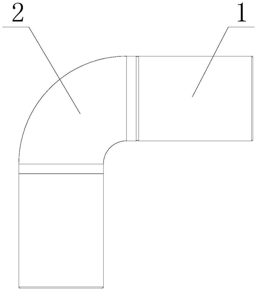
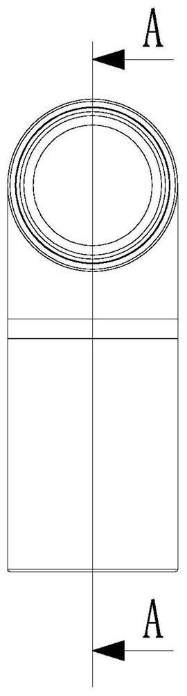
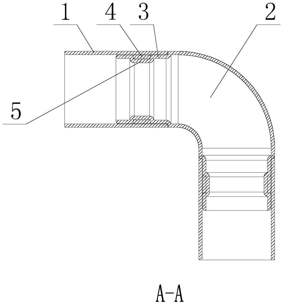
[0033] like Figure 1-3 shown, solder-inset fittings, including

[0034] The pieces to be connected include a first pipe and a second pipe;

[0035] The connection part, which includes the inner extension part where the first pipe piece and the second pipe piece are inserted and overlapped, a section of the inner extension part is deformed outwardly or inwardly to form an annular groove, and the position of the annular groove is inwardly extended between the inner side of the head and the undeformed fitting for placement of solder.

[0036] In this embodiment, the inward extension is the overlapping portion of the first pipe and the second pipe. If the first pipe is on the outside, the inward extension is a part of the second pipe. If the second pipe is on the outside, the inward extension It is a part of the first pipe, and the inner extension is provided with an annular groove, and the annular groove is formed so that the inner extension protrudes outward or inward, for ex...

Embodiment 2

[0038] The annular groove is arranged on the second pipe member and has a concave structure.

[0039] like image 3 As shown, in this embodiment, if the annular groove is on the second pipe member, the annular groove needs to be recessed, and solder can be placed in the recessed annular groove.

Embodiment 3

[0041] The annular groove is arranged on the first pipe member and has an outwardly convex structure.

[0042] like Figure 4 As shown, in this embodiment, if the annular groove is on the first pipe member, the annular groove needs to be convex, and solder can be placed in the convex annular groove.


PUM


Abstract

The invention relates to a pipe internally inlaid with welding flux. The pipe internally inlaid with the welding flux comprises to-be-connected pieces comprising a first pipe piece and a second pipe piece and a connecting portion comprising an internal extension portion which is overlapped during insertion connection of the first pipe piece and the second piece. The internal extension portion is provided with an annular groove used for installing the welding flux. If the annular groove is arranged on the second pipe piece, the annular groove is of an inwards recessed structure. If the annulargroove is arranged on the first pipe fitting, the annular groove is of an outwards protruding structure. The welding flux is in contact connection with the first pipe piece and the second pipe piece.The welding flux is arranged on the overlapped portion of the first pipe piece and the second pipe piece in a sleeving manner. A welding technology comprises the following steps that S1, the welding flux is fed into the annular groove in advance; S2, a heating machine is adopted for heating, and after the welding flux is molten, a pipe piece contact gap is filled; wherein, in the step S1, feedingthe welding flux comprises grooving and filling, the welding flux is silver welding flux and phosphorus-copper welding flux, and the heating machine is a high-frequency heating machine. The pipe internally inlaid with the welding flux and the welding technology have the advantages that penetration depth and firmness of welding are ensured, construction safety is ensured, and the welding difficultyis lowered.

Description

technical field [0001] The invention belongs to the technical field of pipe fitting welding, and in particular relates to a solder-inlaid pipe fitting and a welding process. Background technique [0002] At present, the welding method of domestic copper tubes still adopts open flame heating welding (such as Image 6 ), the biggest disadvantage of this method is: 1. The welding penetration is uneven and the welding is not firm. 2. There will be air holes after welding, and the weak welding is easy to leak (such as Figure 7 ), 3. On-site use of liquefied gas, high risk of open fire construction, 4. Operators have very high technical requirements, and the market promotion is difficult; the retrieved patent number is CN201510789633.X, the public date is 2017.09.15, and the patent name is a A published material on the welding and assembly method of the upper cover of the air-conditioning compressor, which describes a welding and assembling method of the upper cover of the air-co...

Claims


Application Information

Patent Timeline
Patent Type & Authority Applications(China)
IPC IPC(8): B23K33/00B23K1/00B23K1/18
CPCB23K33/00B23K1/00B23K1/18B23K33/006
Inventor 喻曙光许明泰崔秀玲
Owner XINXIANG FENGXIN METAL PROD CO LTD
Why Eureka
Try Eureka