
Method for controlling coaxiality between components

A control method and coaxiality technology, which is applied in the field of coaxiality control between parts and components, can solve problems such as poor product performance, product failure, and poor rotation flexibility of parts and components, and achieve good dimensional consistency and rotation flexibility Good, high tool durability effect

Active Publication Date: 2020-10-13
GUIZHOU HONGLIN MACHINERY
View PDF4 Cites 0 Cited by
  • Summary
  • Abstract
  • Description
  • Claims
  • Application Information

AI Technical Summary

Problems solved by technology

[0003] The company has failed to effectively solve the problem of poor product performance caused by the poor rotation flexibility of the component for many years, and has been repeatedly reported by users that the product is faulty
[0004] Therefore, through the research of product design drawings, our company's engineers found that the reason for the poor rotation flexibility of the component and the failure of the product with multiple feedbacks was that the product design drawings did not stipulate the requirements for rotation flexibility or coaxiality; During the welding process, the requirements for the coaxiality between the porous parts are not identified and not effectively controlled. If the coaxiality between the parts is not well controlled during the machining process and the welding process, the rocker arm will rotate after assembling the drive shaft inflexibility problem

Method used


Image

  • Method for controlling coaxiality between components
  • Method for controlling coaxiality between components
  • Method for controlling coaxiality between components

Examples


Embodiment Construction

[0037] The present invention will be further described below in conjunction with the accompanying drawings and embodiments, but not as a basis for limiting the present invention.

[0038] Example. A method for controlling the coaxiality between parts and components, consisting of Figure 1-7 shown, including the following steps:

[0039] (1) Machining process:

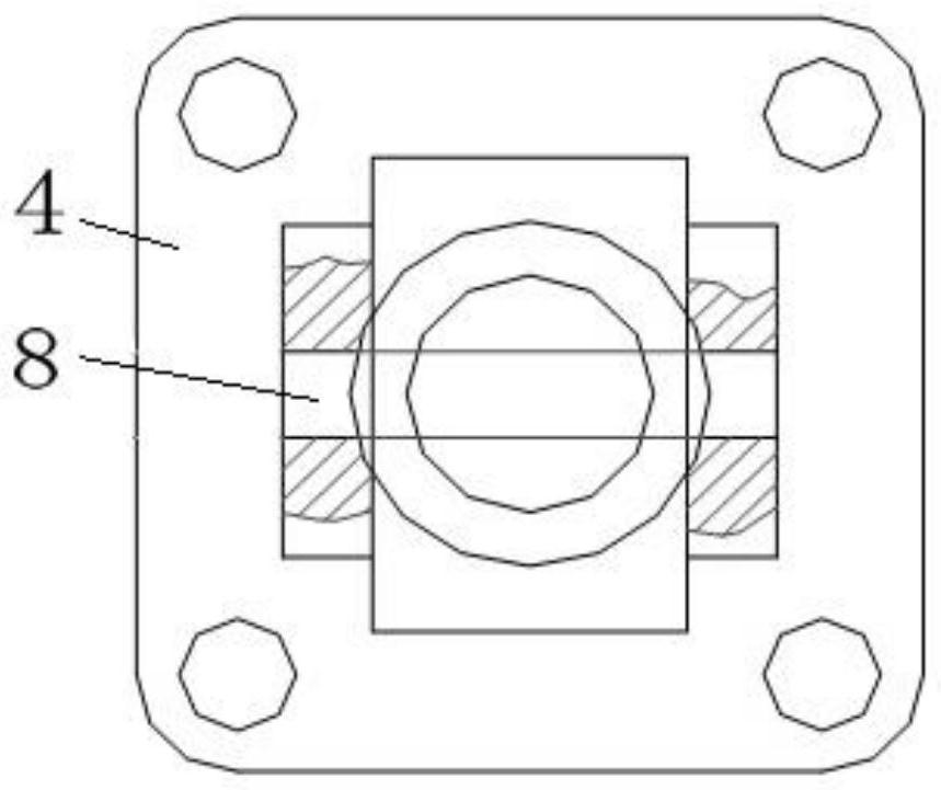
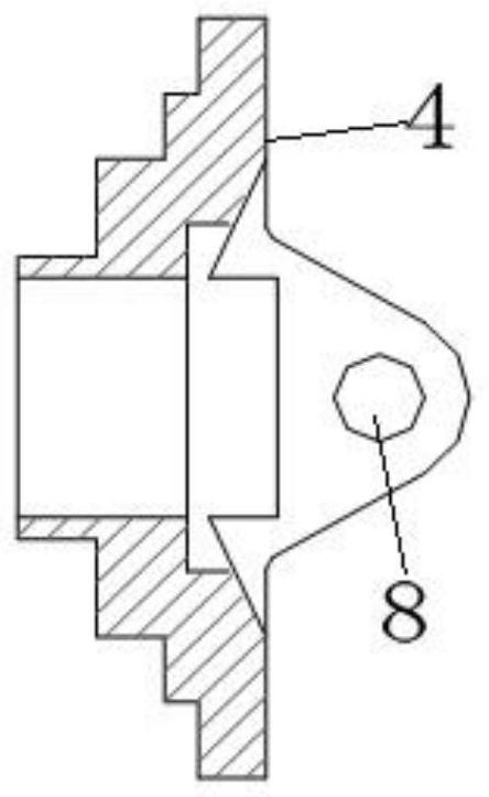
[0040] 1.1 Use the 2 ΦA holes 8 on the reamer bracket 4 of the long-bladed hard alloy reamer with end teeth;

[0041] 1.2 Use the extended grinding sleeve to grind the hole or the extended honing bar to honing the two ΦA holes 8 on the bracket 4;

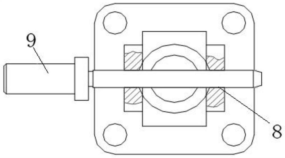
[0042] 1.3 Use the first coaxiality mandrel 9 to measure the coaxiality between the two ΦA holes 8 on the bracket 4;

[0043] (2) Welding process:

[0044] 2.1 Put the open retaining ring 6 and the bearing 5 into the bearing hole of the rocker arm 1 to form a rocker arm assembly;

[0045] 2.2 Use the second coaxiality mandrel 10 to penetrate the rocker arm assembly and...


PUM


Abstract

The invention discloses a method for controlling the coaxiality between components. The method comprises the following steps that (1) a machining process is carried out, specifically, 1.1, two fai A holes are reamed in a support by using a reamer; 1.2, two fai A holes in the support are subjected to finish machining; 1.3, the coaxiality between the two fai A holes in the support is measured by using a first coaxiality core rod; (2) a welding process is carried out, specifically, 2.1, a split washer and a bearing are assembled into a bearing hole of a rocker arm to form a rocker arm assembly; 2.2, a second coaxiality core rod is used for penetrating the rocker arm assembly formed in the step 2.1 and adjusting pieces into the support to be preassembled; and 2.3, the second coaxiality core rod penetrates into a left hole of a mounting hole in a clamp. The method for controlling the coaxiality between the components has the beneficial effects that the method has the advantages of being wide in adaptability and easy to operate, the coaxiality percent of pass can be increased, the production efficiency can be improved, and it can be guaranteed that the rotation flexibility is good when the components rotate with a transmission shaft as the center, so that the performance index of the whole products is improved.

Description

technical field [0001] The invention relates to a method for controlling the coaxiality, in particular to a method for controlling the coaxiality between components. Background technique [0002] In the process of assembly and use of parts and components, there is a need to meet the requirements of rotational flexibility after assembly of parts and components. Since the parts and components are assembled by welding parts such as machined parts and bearings, it involves machining, welding, Assembly and other links, and the batch is large. [0003] The company has failed to effectively solve the problem of poor product performance due to poor rotation flexibility of the component for many years, and users have repeatedly reported that the product is faulty. [0004] Therefore, through the research of product design drawings, our company's engineers found that the reason for the poor rotation flexibility of the component and the failure of the product with multiple feedbacks w...

Claims


Application Information

Patent Timeline
Patent Type & Authority Applications(China)
IPC IPC(8): B23P17/00
CPCB23P17/00
Inventor 张再力杨一峰黄建斌钱春旸李剑段志杰王家谨李怡单金光
Owner GUIZHOU HONGLIN MACHINERY
Learn More