Dual-layer gas pipe, and connection structure and manufacturing method thereof

A technology for gas pipelines and connecting structures, which is applied to non-removable pipe connections, manufacturing tools, sealing surface connections, etc., can solve the problems of high processing cost, increased material cost, wall thickness, etc., and achieves low processing accuracy requirements. , The effect of smooth and fast gas export and low material cost

Active Publication Date: 2020-10-13
CRRC DALIAN CO LTD
View PDF7 Cites 3 Cited by
  • Summary
  • Abstract
  • Description
  • Claims
  • Application Information

AI Technical Summary

Problems solved by technology

When steel pipes are used for both the inner and outer pipes, the spherical sealing form adopted in this scheme may cause failure
lead to limited application
[0005] Second, in order to process the spherical seal on the inner pipe head, and use threaded connection between the expansion sleeve and the inner pipe head, the wall thickness of the inner pipe head must be very thick, which increases the material cost, and the processing accuracy of the spherical seal is relatively high. High, high processing cost
From the structural diagram of this scheme, it can be seen that the cross-sectional area of ​​the gas outlet at the end is smaller than the interlayer cross-sectional area between the inner and outer pipes, and the gas is throttled at the end. Once the sealing surface at the end leaks, there will be A large amount of gas leakage, this structure is not conducive to the rapid export of leaked gas

Method used


Image

  • Dual-layer gas pipe, and connection structure and manufacturing method thereof
  • Dual-layer gas pipe, and connection structure and manufacturing method thereof
  • Dual-layer gas pipe, and connection structure and manufacturing method thereof

Examples


Embodiment Construction

[0046] In order to make the purpose, technical solutions and advantages of the present invention clearer, the embodiments of the present invention will be further described in detail below in conjunction with specific embodiments and with reference to the accompanying drawings.

[0047] It should be noted that all expressions using "first" and "second" in the embodiments of the present invention are used to distinguish two entities with the same name but different parameters or parameters that are not the same, see "first" and "second" It is only for the convenience of expression, and should not be construed as a limitation on the embodiments of the present invention, which will not be described one by one in the subsequent embodiments.

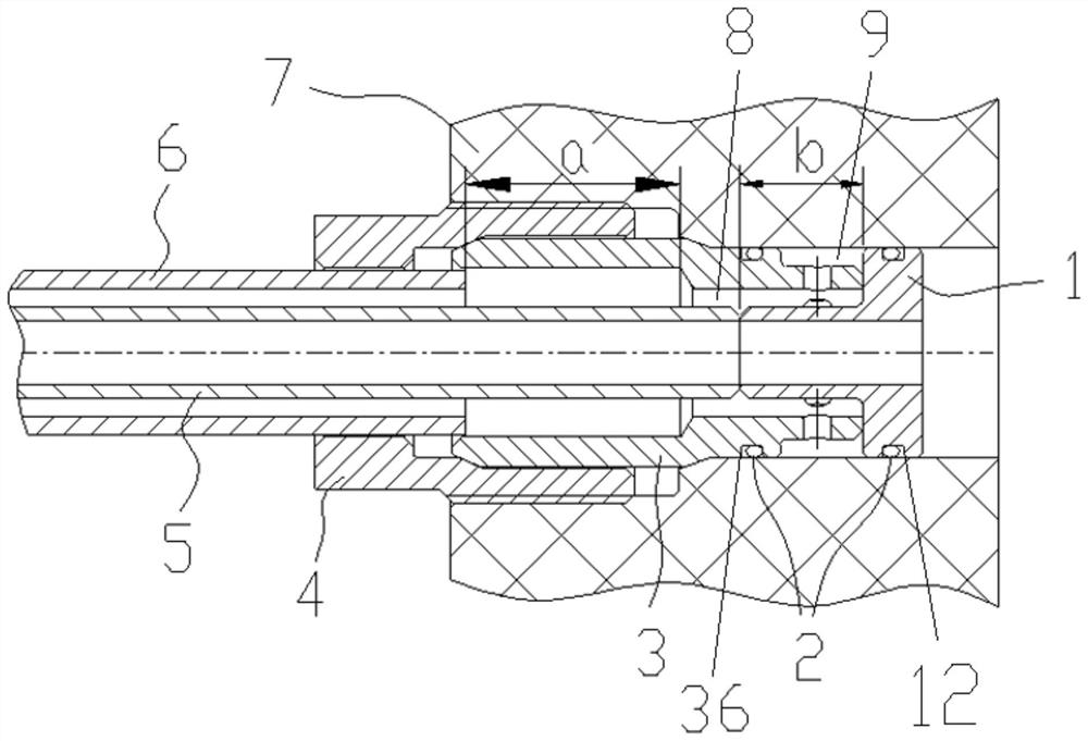
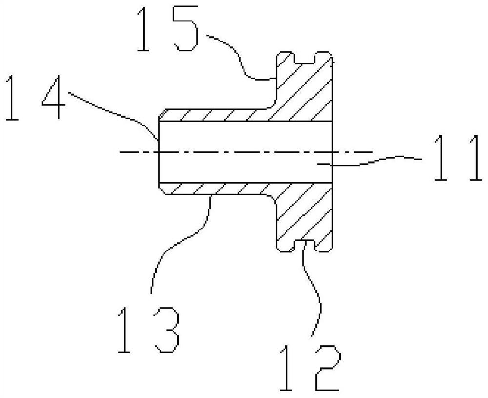
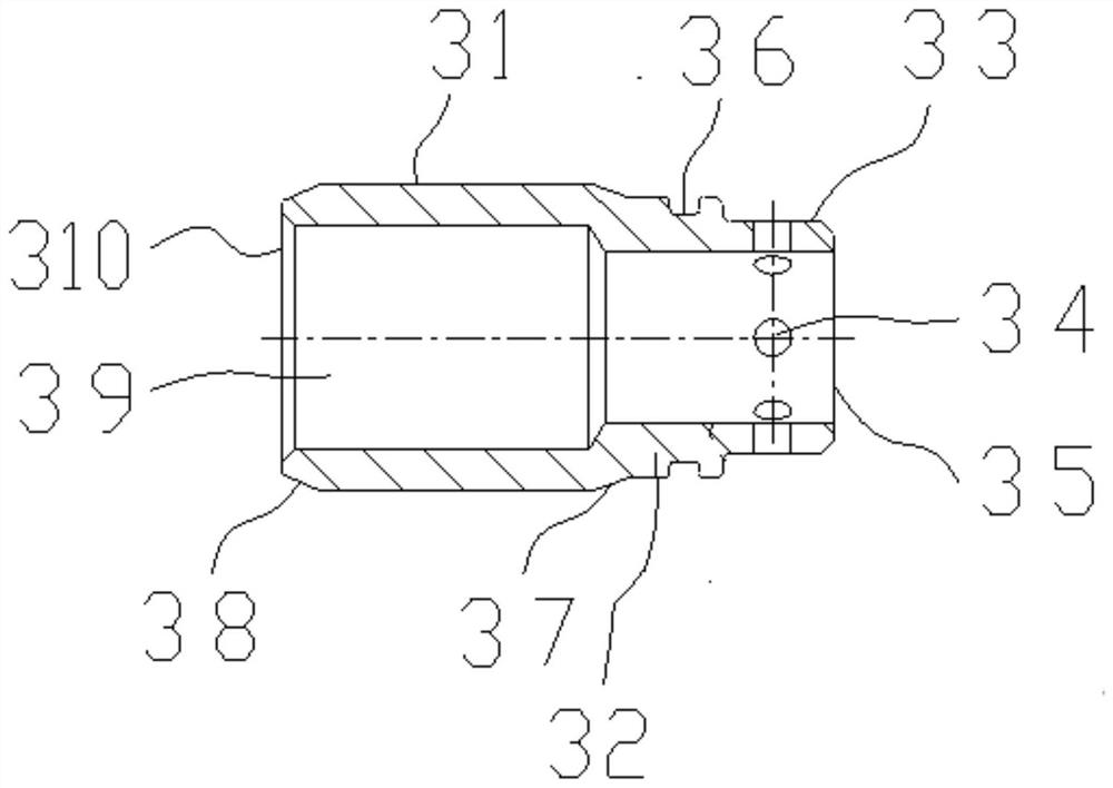
[0048] Such as Figure 1 to Figure 4 As shown, some embodiments of the present invention disclose a connection structure for connecting a double-layer gas pipeline to an external interface and a double-layer gas pipeline, which includes an in...


PUM


Abstract

The invention discloses a dual-layer gas pipe, and a connection structure and a manufacturing method thereof. The dual-layer gas pipe comprises an inner joint, an outer joint and a connection body. The head end of the inner joint is connected with the tail end of an inner-layer pipe. The head end of the outer joint is connected with the tail end of an outer-layer pipe. The tail end of the outer joint is connected with the outer wall of the inner joint. A first cavity is formed between the inner wall of the outer joint, the inner joint and part of the outer wall of the inner-layer pipe. A gas guide hole is formed in the part, forming the first cavity, of the wall of the outer joint. The outer joint is inserted into an external connecting piece. A second cavity is formed between the inner wall of the external connecting piece and the outer wall of the outer joint and at the position of the gas guide hole. The outer-layer pipe is sleeved with the connection body, and the connection body is used to be detachably connected with the external connecting piece. According to the dual-layer gas pipe, and the connection structure and the manufacturing method thereof, the structure is simple,and the requirements on installation are common; the inner-layer pipe and the outer-layer pipe can be used in cooperation with steel pipes as well as metal hoses, and the adaptability to different application occasions is high; the requirement on the processing accuracy is not high, and the processing cost and the material cost are low; and no throttling is carried out on a guide-out part for thegas which leaks out, and therefore, the gas can be guided out smoothly and quickly.

Description

technical field [0001] The invention relates to the technical field of gas transportation, in particular to a double-layer gas pipeline and its connecting structure and manufacturing method. Background technique [0002] As the gas is a dangerous gas, if it reaches a certain concentration in the environment, it will explode when exposed to an open flame, causing harm to surrounding equipment, personnel and the environment. For gas pipelines, preventing the internal gas from leaking to the outside is the focus of safety protection. To minimize the risk of gas leakage, the use of double-layer gas lines is an effective solution. When the inner tube of the double-layer pipeline used to transport gas is damaged, it will flow into the interlayer between the inner and outer tubes, and then discharge the gas to a safe area through the interlayer, thus ensuring that the gas will not leak directly to the outside environment, ensuring safety. [0003] Existing double-walled gas pipe...

Claims


Application Information

Patent Timeline
Patent Type & Authority Applications(China)
IPC IPC(8): F16L39/00F16L13/02F16L19/07F16L19/075B23K33/00
CPCF16L39/005F16L13/02F16L19/005F16L19/063F16L19/07F16L19/075B23K33/00
Inventor 吕晓东张双成刘艳朝赵慧恩尹欢高洋
Owner CRRC DALIAN CO LTD
Why Eureka
Try Eureka