Drying oven for spinning

An oven and textile technology, applied in the textile field, can solve the problems of short drying path, long drying time, and small range, and achieve the effects of sufficient drying, high drying efficiency, and expanded drying range

Inactive Publication Date: 2020-10-13
诸暨市众创机械设备厂
View PDF5 Cites 12 Cited by
  • Summary
  • Abstract
  • Description
  • Claims
  • Application Information

AI Technical Summary

Problems solved by technology

[0003] During the textile process, the fabric needs to be dried. The existing ovens generally use fixedly installed electric heating elements and fans for drying. The drying path is short and the range is small, resulting in long drying time and low efficiency.

Method used


Image

  • Drying oven for spinning
  • Drying oven for spinning
  • Drying oven for spinning

Examples


Embodiment 1

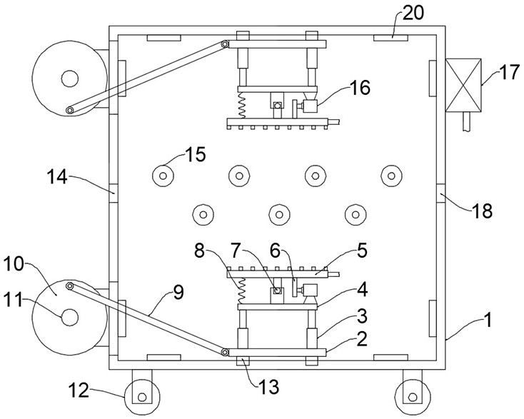
[0023] see Figure 1~2 , in the embodiment of the present invention, a textile oven includes a box body 1 and a drying unit, the bottom of the box body 1 is evenly and symmetrically fixed with rollers 12, and the rollers 12 are self-locking rollers, which facilitate the movement of the device. A box door is installed on the box body 1. In this embodiment, the box door is preferably installed on the box body 1 by hinges and hasps, and the symmetrical side walls of the box body 1 are respectively provided with openings for textile movement. Inlet 14 and outlet 18, further, in order to extend the drying path, a plurality of guide rollers 15 are installed in the box body 1 at the upper and lower sides of the inlet 14 and outlet 18, and the drying unit includes 1. The electric heating element 20 on the inner wall also includes an air-drying assembly located at the top and bottom of the inner cavity of the box body 1. The air-drying assembly includes a drying plate 5 and a driving m...

Embodiment 2

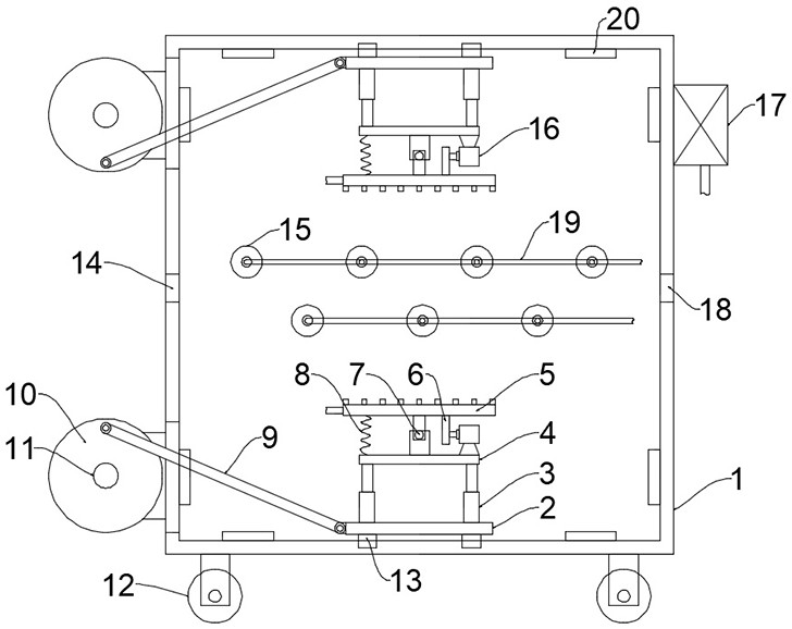
[0025] see image 3 The difference between the embodiment of the present invention and embodiment 1 is that the inside of the guide roller 15 is hollow and a plurality of spray holes are evenly opened on it, the guide roller 15 is connected with a second soft air pipe 19, and the second soft air pipe 19 The other end communicates with the air outlet of the hot air blower 17 to further dry the cloth with high drying efficiency.

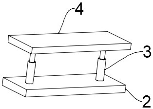
[0026] The working principle of the present invention is: the cloth is passed through the guide roller 15 through the inlet 14 and finally passed through the outlet 18. When drying, the second motor 11 drives the turntable 10 to rotate, and the turntable 10 drives the first installation through the connecting rod 9. The reciprocating movement of the plate 2 can expand the drying range and improve the drying efficiency. The distance between the drying plate 5 and the cloth can be adjusted by extending or shortening the electric push rod 3. The first mot...


PUM


Abstract

The invention discloses a drying oven for spinning. The drying oven comprises an oven body and a drying unit, and further comprises air drying assemblies positioned at the top and the bottom of an inner cavity of the oven body, wherein each air drying assembly comprises a drying plate and a drive module used for driving the drying plate to move; each drive module comprises a reciprocating motion mechanism, a lifting mechanism and a swing mechanism; the reciprocating motion mechanism is in drive connection with the lifting mechanism; the lifting mechanism is in drive connection with the swing mechanism; the swing mechanism is in drive connection with the drying plate; the air drying assemblies are arranged; a second motor drives a rotary disc to rotate, the rotary disc drives a first installing plate to reciprocate through a connecting rod, the drying range can be enlarged, and the drying efficiency is improved; through electric push rod stretching or shortening, the distance between the drying plates and cloth can be adjusted; and a first motor drives a cam to rotate, the cam is matched with a spring to drive the drying plates to swing, the air spraying angle can be constantly changed, drying is more sufficient and uniform, and the drying efficiency is high.

Description

technical field [0001] The invention relates to the technical field of textiles, in particular to an oven for textiles. Background technique [0002] The original meaning of textile is taken from the general term of spinning and weaving, but with the continuous development and improvement of the textile knowledge system and subject system, especially after the emergence of non-woven textile materials and three-dimensional composite weaving technologies, it is not only the traditional hand spinning And weaving, also including non-woven fabric technology, modern three-dimensional weaving technology, modern electrostatic nano-netting technology and other clothing, industrial and decorative textiles. Therefore, modern textile refers to a multi-scale structure processing technology of fibers or fiber aggregates. [0003] During the weaving process, the fabric needs to be dried. The existing ovens generally use fixedly installed electric heating elements and fans for drying. The ...

Claims


Application Information

Patent Timeline
Patent Type & Authority Applications(China)
IPC IPC(8): F26B13/08F26B13/10F26B21/00F26B25/10F26B25/12F26B13/16
CPCF26B13/08F26B13/10F26B13/16F26B21/004F26B25/10F26B25/12
Inventor 刘欢红
Owner 诸暨市众创机械设备厂
Why Eureka
Try Eureka