
Magnetic engine

An engine and magnetic technology, applied in electromechanical devices, electrical components, etc., can solve the problems of fuel pollution, waste of energy, resource depletion, etc., and achieve the effect of relieving power supply pressure, stable output energy, and high use value

Inactive Publication Date: 2020-10-13
张元志
View PDF0 Cites 2 Cited by
  • Summary
  • Abstract
  • Description
  • Claims
  • Application Information

AI Technical Summary

Problems solved by technology

[0003] At present, the engine is still dominated by internal combustion engines. Whether it is a gasoline engine or a diesel engine, carbonaceous fuels are used as energy sources. During the use of internal combustion engines, incomplete combustion or insufficient combustion of fuel will cause pollution. Carbon dioxide, one of the products of combustion, will Exacerbate the greenhouse effect; the efficiency of internal combustion engines is generally relatively low, which seriously wastes energy and increases the operating cost of the engine
In addition, oil and natural gas are non-renewable resources, and long-term use will cause the depletion of these resources
[0004] In order to solve the above problems, the magnetic engine, as a new type of renewable clean energy engine, has been proposed many years ago. However, due to the large additional work done by its own friction and gravity, the output of useful work is not much. , has not been widely used

Method used


Image

  • Magnetic engine
  • Magnetic engine
  • Magnetic engine

Examples


Embodiment Construction

[0022] The technical solutions of the present invention will be clearly and completely described below in conjunction with the embodiments. Obviously, the described embodiments are part of the embodiments of the present invention, but not all of them. Based on the embodiments of the present invention, all other embodiments obtained by persons of ordinary skill in the art without making creative efforts belong to the protection scope of the present invention.

[0023] In describing the present invention, it is to be understood that the terms "center", "longitudinal", "transverse", "length", "width", "thickness", "upper", "lower", "front", " Back", "Left", "Right", "Straight", "Horizontal", "Top", "Bottom", "Inner", "Outer", "Clockwise", "Counterclockwise", etc. or The positional relationship is based on the orientation or positional relationship shown in the drawings, which is only for the convenience of describing the present invention and simplifying the description, rather t...


PUM


Abstract

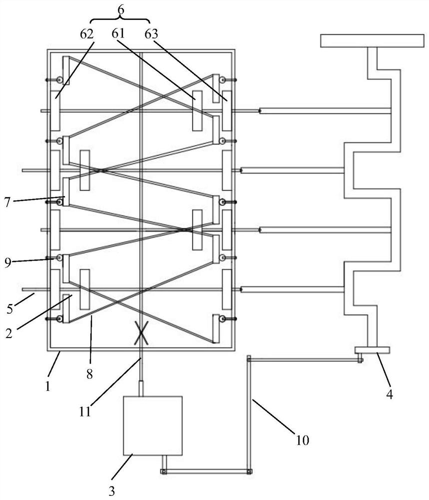
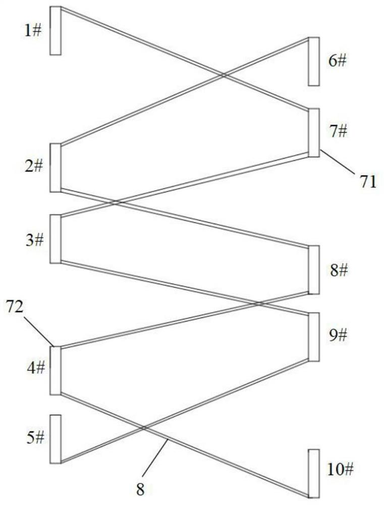
The invention provides a magnetic engine which comprises a box body, a power device, a delay device and a crankshaft, the power device comprises a plurality of groups of power mechanisms connected inparallel, each power mechanism comprises a transmission shaft, magnetic plate groups and an iron plate, the magnetic plate groups are arranged in parallel, each magnetic plate group comprises two stator magnetic plates fixed on two opposite side surfaces of the box body and a rotor magnetic plate in the box body, and two side surfaces of each rotor magnetic plate respectively repel the adjacent stator magnetic plates in magnetism; the iron plates are positioned between two adjacent magnetic plates, are parallel to the magnetic plates, and can move relative to the magnetic plates to change themagnetic induction line flux between the stator magnetic plates and the rotor magnetic plates, so that the rotor magnetic plates are stressed unevenly to move; the transmission shafts vertically penetrate through the magnetic plates and the iron plates, the end parts of the transmission shafts extend out of the box body and are connected with the crankshaft, and the transmission shafts are used for driving the crankshaft to rotate to output power; the delay device transmits output power to drive the iron plates to move so as to shield magnetic lines of force. The magnetic force balance point is broken, the magnetic energy is released, and the magnetic engine can be widely applied to daily production and life.

Description

technical field [0001] The invention relates to the technical field of motors, in particular to a magnetic motor. Background technique [0002] An engine is a machine that can convert other forms of energy into mechanical energy, usually by converting chemical energy into mechanical energy, and using the deflagration of fuel to push the piston to reciprocate, so as to achieve the purpose of converting the chemical energy of the fuel into the kinetic energy of the piston. [0003] At present, the engine is still dominated by internal combustion engines. Whether it is a gasoline engine or a diesel engine, carbonaceous fuels are used as energy sources. During the use of internal combustion engines, incomplete combustion or insufficient combustion of fuel will cause pollution. Carbon dioxide, one of the products of combustion, will Intensify the greenhouse effect; the use efficiency of the internal combustion engine is generally relatively low, which seriously wastes energy and ...

Claims


Application Information

Patent Timeline
Patent Type & Authority Applications(China)
IPC IPC(8): H02K53/00
CPCH02K53/00
Inventor 张元志
Owner 张元志
Learn More