Method for testing conducted interference characteristic simulation model based on power electronic transformer system

A technology of conduction interference and simulation model, which is applied in the fields of adjusting electrical variables, control/adjustment system, design optimization/simulation, etc. It can solve the problems that the simulation test method cannot be directly applied, the lack of PET conduction interference, and the measurement results are not in line with reality, etc., to achieve The effect of shortening the R&D cycle, ensuring correctness, and reducing development costs

Active Publication Date: 2020-10-13
TONGJI UNIV
View PDF2 Cites 1 Cited by
  • Summary
  • Abstract
  • Description
  • Claims
  • Application Information

AI Technical Summary

Problems solved by technology

[0004] At present, most of the research on PET in academia and industry focuses on system control and topology research, and there is a lack of technical research on PET conduction interference.
However, there are mainly the following problems in the technical research on PET conducted interference: 1. The existing simulation models can only focus on the relatively simple single-stage power converter structure, and lack the relevant conducted interference for more complex systems like PET. Model establishment; 2. The simulation test method for conducted interference cannot be directly applied to the interference test of multi-level systems. For example, on the DC side of the PET system, it is directly connected to the rectification stage and isolation stage of the system. Interference, plus LISN (Linear Impendence Stabilization Network) measurement will inevitably bypass the conduction interference generated by one side, resulting in unrealistic measurement results

Method used


Image

  • Method for testing conducted interference characteristic simulation model based on power electronic transformer system
  • Method for testing conducted interference characteristic simulation model based on power electronic transformer system
  • Method for testing conducted interference characteristic simulation model based on power electronic transformer system

Examples


Embodiment Construction

[0042] The present invention will be described in detail below in conjunction with the accompanying drawings and specific embodiments. This embodiment is carried out on the premise of the technical solution of the present invention, and detailed implementation and specific operation process are given, but the protection scope of the present invention is not limited to the following embodiments.

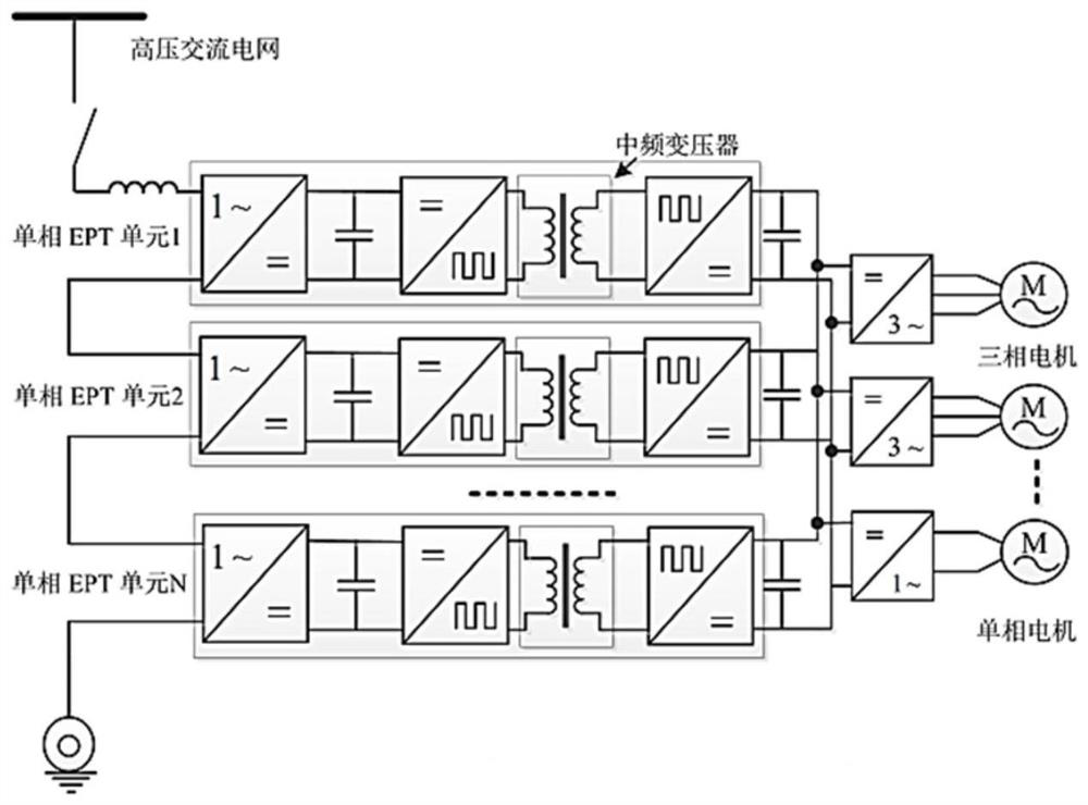
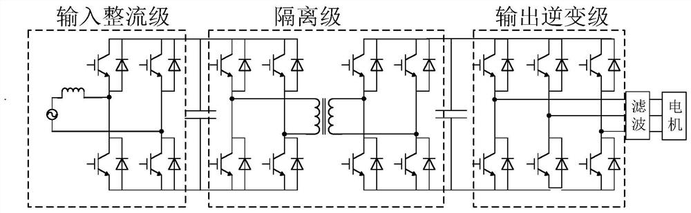
[0043] This embodiment provides a test method based on a simulation model of conduction disturbance characteristics of a power electronic transformer system (PET). In this embodiment, under the premise of ensuring the normal operation of the PET system, the conduction interference characteristics of the system as a whole and different levels within the system can be simulated and tested, and the characteristics and mutual influences of the interference generated by the system as a whole and different levels within the system can be grasped. So as to clearly grasp the specific mechanis...


PUM


Abstract

The invention relates to a method for testing a conducted interference characteristic simulation model based on a power electronic transformer system. The method comprises the following steps: establishing a system rectifier stage model; establishing a system isolation level model by adopting a double-active-bridge DC/DC converter structure through a phase shift control method; constructing an operation simulation model in simulation software through the system rectification-level model and the system isolation-level model; considering a high-frequency model of a passive device in the power electronic transformer system, extracting main parasitic parameters in the circuit structure, and establishing a high-frequency simulation model of conduction interference of the power electronic transformer system; arranging a first resistance-capacitance branch and a second resistance-capacitance branch in the high-frequency simulation model to measure conducted interference. Compared with the prior art, the simulation test of the conducted interference can be conveniently and quickly carried out on the PET system comprising two or more power conversion links, meanwhile, the conducted interference characteristics independently generated by different power conversion links in the same system can also be tested, and the accuracy is high.

Description

technical field [0001] The invention relates to the field of power electronic transformer system simulation, in particular to a simulation model testing method based on conduction interference characteristics of the power electronic transformer system. Background technique [0002] In recent years, with the rapid development of power electronics technology, more and more power electronic converters have been applied to the field of power systems, distributed in all links of power generation, transmission, and distribution, making power systems face many new requirements and challenges . In this regard, the traditional power frequency transformer will be difficult to meet the requirements due to its single function, and the power electronic transformer (Power Electronic Transformer, PET) has been developed rapidly due to its unique structure and excellent functions, and has been favored by academia and Widely recognized by the industry. Such as figure 1 Shown is a PET-base...

Claims


Application Information

Patent Timeline
Patent Type & Authority Applications(China)
IPC IPC(8): H02M7/219H02M3/335H02M1/44G06F30/20
CPCG06F30/20H02M1/44H02M3/33584H02M7/219
Inventor 康劲松朱玺元陈涛梁玉毛中亚
Owner TONGJI UNIV
Why Eureka
Try Eureka