Pixel structure of a retina-like image sensor

An image sensor and pixel structure technology, applied in the field of pixel structure, can solve the problems of time stamp mismatch, easy delay, and cannot be removed, so as to eliminate the influence of reset noise, reduce the amount of data, and eliminate motion artifacts Effect

Active Publication Date: 2021-05-25
上海宇勘科技有限公司
View PDF12 Cites 0 Cited by
  • Summary
  • Abstract
  • Description
  • Claims
  • Application Information

AI Technical Summary

Problems solved by technology

[0016] In order to solve the existing method, the present invention uses asynchronous real-time detection of light intensity changes for each pixel, and adopts the AER event readout method, which is prone to delays, resulting in mismatches between events and corresponding time stamps, and motion artifacts; And it is easy to be affected by the leakage current of the transistor to generate false events, and it cannot be removed, etc., providing a pixel structure similar to the retinal image sensor

Method used


Image

  • Pixel structure of a retina-like image sensor
  • Pixel structure of a retina-like image sensor
  • Pixel structure of a retina-like image sensor

Examples


specific Embodiment approach 1

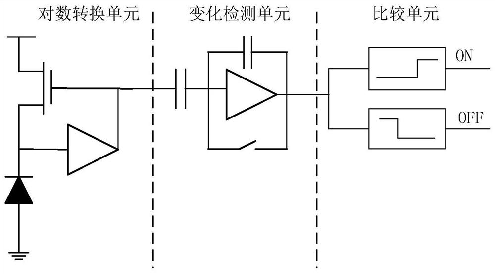
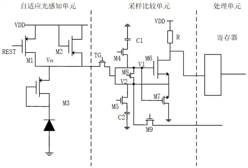
[0040] Specific implementation mode 1. Combination Figure 1 to Figure 3 Describe this embodiment, a retina-like image sensor pixel structure. This embodiment is based on the working principle of the biological retina and consists of three cascaded parts. The first stage uses an adaptive light-sensing structure to complete the conversion of optical signals to electrical signals. Partially similar to the cone cells in the retina, it is used to sense light intensity and perform photoelectric conversion. The second stage is the sampling comparison circuit similar to the bipolar cells in the retina, which completes the sampling and comparison functions to determine the signal polarity. When the light intensity becomes weaker, an OFF signal is generated, and when the light intensity becomes stronger, an ON signal is generated. The third level is the pixel-level signal processing unit, which is similar to the human visual processing unit. It stores the polarity signal of the upper ...

specific Embodiment approach 2

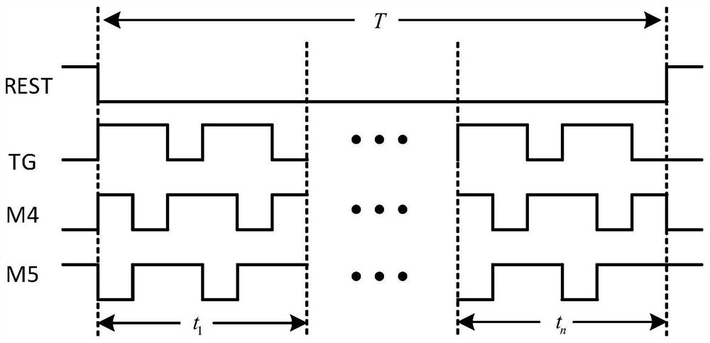
[0075] Specific embodiment two, combine Figure 4 This embodiment is described. This embodiment is the method for controlling the transfer signal of the pixel structure of the retinal image sensor described in Embodiment 1. The method is implemented by the following steps:

[0076] A. Perform a global reset, and the adaptive light sensing unit adaptively selects the response mode according to the magnitude of the light intensity;

[0077] B. Turn on the transmission tube TG, then turn on the transistor M4 in turn, and the transistor M5 performs integration, then close the transmission tube TG, and send the integral value into the comparison circuit composed of the transistor M6 and the transistor M7, so as to form the ON / OFF corresponding to the light intensity change OFF event;

[0078] C. The signal processing unit stores ON / OFF events, and performs event preprocessing according to the instructions, and waits for column scanning to be read out;

[0079] D. After the column...


PUM


Abstract

A kind of pixel structure of a retinal image sensor, related to the field of integrated circuits. The existing method uses asynchronous real-time detection of light intensity changes for each pixel, and uses the AER event readout method, which is prone to delays, resulting in events and corresponding events. The time stamps do not match, resulting in motion artifacts; and it is susceptible to false events caused by the leakage current of the transistor, and cannot be removed. The adaptive light sensing unit is used to complete the conversion of optical signal to electrical signal and output voltage signal; the sampling comparison unit is used to complete the sampling and comparison function to determine the polarity of the signal. When the light intensity becomes weaker, an OFF signal is generated, and the light intensity becomes stronger. The signal processing unit stores the polarity signal output by the sampling comparison unit, and performs signal processing according to the instruction to complete the noise reduction; the present invention eliminates motion artifacts and abandons the asynchronous readout method of the traditional dynamic visual sensor, Grayscale images can also be output while outputting events.

Description

technical field [0001] The invention relates to the field of integrated circuits, in particular to a pixel structure of a retinal image sensor. Background technique [0002] Traditional image sensors perform imaging in frames. Compared with the previous frame, regardless of whether the pixels have changed, a series of processing such as exposure, sampling, and amplification must be performed on all pixels. There is a lot of repetitive work. High data redundancy. Moreover, due to the limitation of the frame rate, the image information of the high-speed moving object is easily lost in the frame-to-frame interval. [0003] Nowadays, the mainstream imaging devices are CCD and CMOS image sensors. Their pixel structure is simple, small in size, which is conducive to improving image resolution, and output images in frame imaging mode, so that the output images are more intuitive and can better please people. Eye. But the frame-based imaging mode also has the following inherent d...

Claims


Application Information

Patent Timeline
Patent Type & Authority Patents(China)
IPC IPC(8): H04N5/213H04N5/341H04N5/907
CPCH04N7/005H04N5/213H04N5/907H04N25/40
Inventor 吕恒毅张以撒冯阳赵宇宸孙铭
Owner 上海宇勘科技有限公司
Why Eureka
Try Eureka