Protective device for orthopedic spine
A protection device and spine technology, applied in the field of orthopedic spine protection devices, can solve problems such as poor correction and protection of the spine, limited correction of the cervical spine, and failure to achieve protection effects, etc., to improve rehabilitation effects, massage effects, and convenience. Check the effect
- Summary
- Abstract
- Description
- Claims
- Application Information
AI Technical Summary
Problems solved by technology
Method used
Image
Examples
Embodiment 1
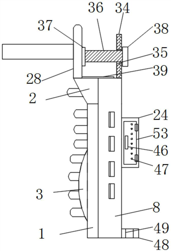
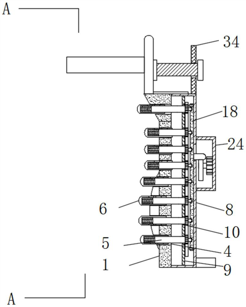
[0041] see Figure 1-13 , according to an embodiment of the present invention, an orthopedic spine protection device includes a vertical plate 1, the top of the vertical plate 1 is fixedly connected with a top plate 2, and the bottom of one side of the vertical plate 1 is fixedly connected with an arc convex plate 3 , the surface of the vertical plate 1, the top plate 2 and the curved convex plate 3 are all provided with a through hole 4, the inside of the through hole 4 is provided with a rotating sleeve 5, and one end of the rotating sleeve 5 is covered with a massage cover 6, so The port of the massage cover 6 is located outside the through hole 4, and it should be noted that the port of the massage cover 6 located outside the through hole 4 is a spherical surface;
[0042] A limiting mechanism is connected between the massage cover 6 and the rotary cover 5, a spring 7 is connected between the inside of the massage cover 6 and the port of the rotary cover 5, the vertical pl...
Embodiment 2
[0048] see Figure 1-2 and Figure 10 , the adjustment mechanism includes a support plate 34, a screw hole 35, a screw rod 36, a bearing 2 37 and a rotating block 38, the top of the fixed box 8 is fixedly connected with a support plate 34, and the inside of the support plate 34 has a screw hole 35, the internal thread of the screw hole 35 is connected with a screw 36, one end of the screw 36 is connected to the bonding plate 28 through a bearing 2 37, the other end of the screw 36 is fixedly connected to the rotating block 38, and the adjusting mechanism The position of the fitting plate 28 can be adjusted, so that the fitting plate 28 can be in close contact with the wearer's head, thereby achieving the purpose of limiting. The top of the top plate 2 and the vertical plate 1 are fixedly connected with a limit rod 39, and the fitting plate 28 and close to the limit bar 39 to open a limit groove 40, the limit bar 39 is located in the limit groove 40 and matches with the limit ...
Embodiment 3
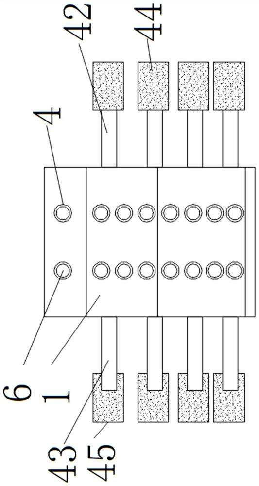
[0050] see image 3 , the binding mechanism includes three binding straps 42, four binding straps 43, two Velcro stickers 44 and two Velcro female stickers 45, one side of the fixed box 8 is fixedly connected with three binding straps 42, and the three binding straps 42 Two Velcro stickers 45 are fixedly connected to the port of the fixed box 8, and one side of the fixed box 8 away from the three straps 42 is fixedly connected with four straps 43, and the port of the four straps 43 is fixedly connected with two Velcro stickers. 44. The second Velcro sticker 45 is matched with the second Velcro sticker 44, and the binding mechanism can fix the device on the wearer's spine, so as to achieve the purpose of fixing, so that the device fits the wearer's spine.
PUM
 Abstract
Description
Claims
Application Information
 - R&D
- Intellectual Property
- Life Sciences
- Materials
- Tech Scout
- Unparalleled Data Quality
- Higher Quality Content
- 60% Fewer Hallucinations
Browse by: Latest US Patents, China's latest patents, Technical Efficacy Thesaurus, Application Domain, Technology Topic, Popular Technical Reports.
© 2025 PatSnap. All rights reserved.Legal|Privacy policy|Modern Slavery Act Transparency Statement|Sitemap|About US| Contact US: help@patsnap.com


