Rehabilitation exercise machine with lumbar vertebra supporting function and using method
A technology of lumbar support and exercise machine, applied in the field of physical rehabilitation exercise
- Summary
- Abstract
- Description
- Claims
- Application Information
AI Technical Summary
Problems solved by technology
Method used
Image
Examples
Embodiment 1
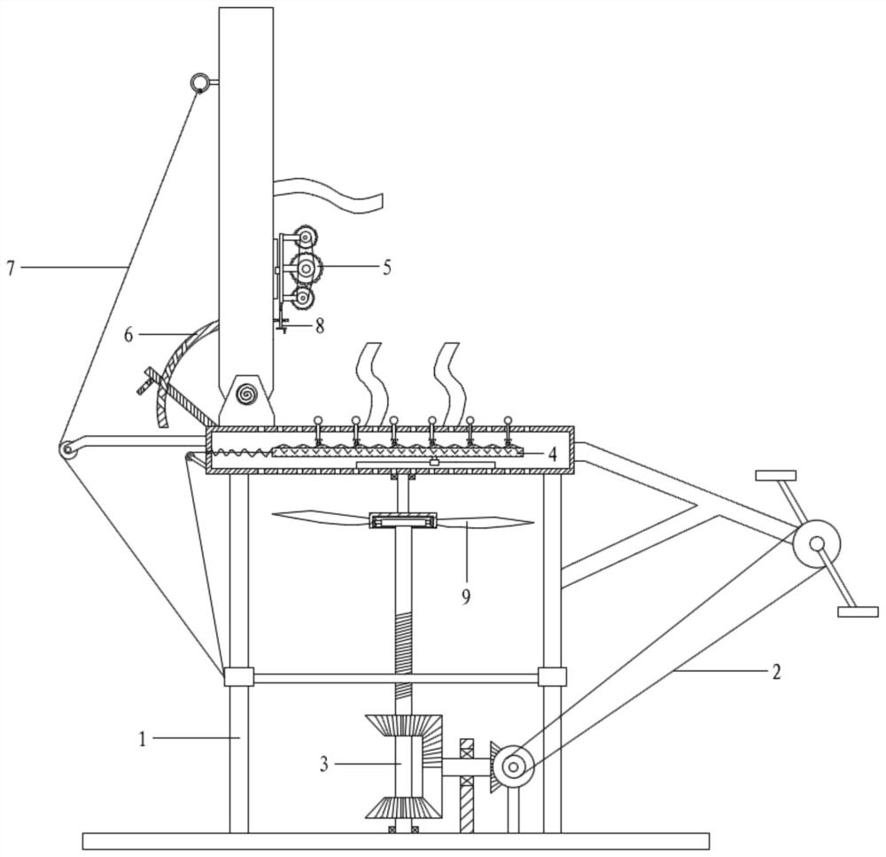
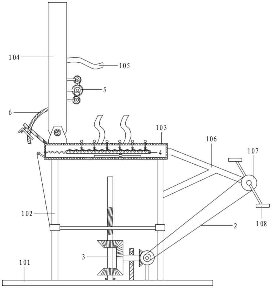
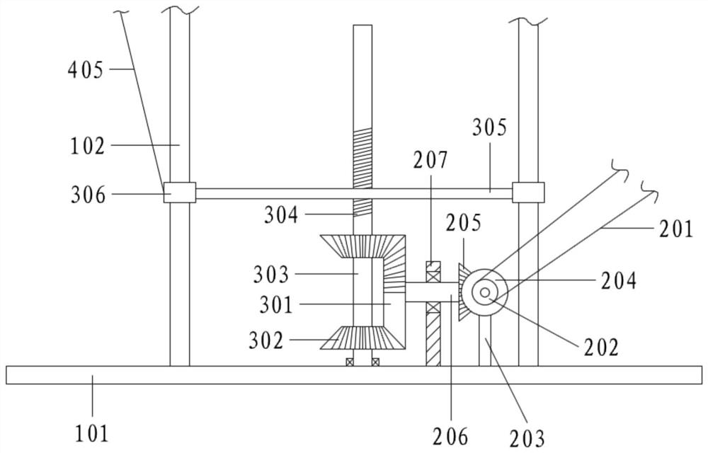
[0068] Referring to the accompanying drawings, a rehabilitation exercise machine with a lumbar support function includes a bracket assembly 1, a transmission assembly 2, a reciprocating assembly 3, a hip massage assembly 4, a lumbar support assembly 5 and a positioning assembly 6;
[0069] The bracket assembly 1 includes a base 101, a slide bar 102, a hollow seat plate 103, a backrest 104, a fixing belt 105, a connecting frame 106, a transmission wheel 107 and a pedal 108, and the base 101 is fixed with vertical slide bars 102 at intervals. , the top of the slide bar 102 is connected with a hollow seat plate 103, the left end of the top of the hollow seat plate 103 is hinged to the bottom end of the backrest 104; the hollow seat plate 103 and the backrest 104 are connected with a fixing belt 105; The right end of the connecting frame 106 is equipped with a No. 1 transmission wheel 107, and the No. 1 transmission wheel 107 is equipped with a pedal 108; the base 101 is provided w...
Embodiment 2
[0071] Referring to the accompanying drawings, a rehabilitation exercise machine with a lumbar support function includes a bracket assembly 1, a transmission assembly 2, a reciprocating assembly 3, a hip massage assembly 4, a lumbar support assembly 5 and a positioning assembly 6;
[0072] The bracket assembly 1 includes a base 101, a slide bar 102, a hollow seat plate 103, a backrest 104, a fixing belt 105, a connecting frame 106, a transmission wheel 107 and a pedal 108, and the base 101 is fixed with vertical slide bars 102 at intervals. , the top of the slide bar 102 is connected with a hollow seat plate 103, the left end of the top of the hollow seat plate 103 is hinged to the bottom end of the backrest 104; the hollow seat plate 103 and the backrest 104 are connected with a fixing belt 105; The right end of the connecting frame 106 is equipped with a No. 1 transmission wheel 107, and the No. 1 transmission wheel 107 is equipped with a pedal 108; the base 101 is provided w...
Embodiment 3
[0096] In Embodiment 2, if the backrest 104 forms an obtuse angle with the hollow seat plate 103, the lumbar support assembly 5 will continuously press against the lumbar spine, which will cause a strong sense of discomfort to the initial users.
[0097] Therefore, on the basis of Embodiment 2, an overturn assembly 7 is also provided;
[0098] Turnover assembly 7 includes No. 2 stay cord 701, No. 2 guide wheel 702 and tether ring 703;
[0099] The left end of the hollow seat plate 103 is fixedly connected with the hinge seat 1032, and the bottom end of the backrest 104 is rotationally connected with the hinge seat 1032 through the installation shaft, and a torsion spring 1033 is installed at the joint; the torsion spring 1033 makes the backrest 104 have a tendency to rotate clockwise; the hollow seat plate No. 2 guide wheel 702 is also installed on the left side of 103, and a tether ring 703 is fixed on the upper left side of the backrest 104; Connect the tether loop 703 to t...
PUM
 Abstract
Description
Claims
Application Information
 - R&D
- Intellectual Property
- Life Sciences
- Materials
- Tech Scout
- Unparalleled Data Quality
- Higher Quality Content
- 60% Fewer Hallucinations
Browse by: Latest US Patents, China's latest patents, Technical Efficacy Thesaurus, Application Domain, Technology Topic, Popular Technical Reports.
© 2025 PatSnap. All rights reserved.Legal|Privacy policy|Modern Slavery Act Transparency Statement|Sitemap|About US| Contact US: help@patsnap.com


