Synchronous multi-cutter fixed-distance cutting device for steel pipe

A technology for cutting devices and steel pipes, which is applied in the direction of pipe shearing devices, shearing devices, and accessories of shearing machines, etc. It can solve the problems of long time-consuming measurement of fixed distances, inconvenient fixed distances, and reduced work efficiency, etc., and achieves a reasonable structure , simple operation, and the effect of improving work efficiency

Pending Publication Date: 2020-10-16
YANGZHOU STRVALUE INFORMATION TECH CO LTD
View PDF10 Cites 5 Cited by
  • Summary
  • Abstract
  • Description
  • Claims
  • Application Information

AI Technical Summary

Problems solved by technology

[0004] The purpose of the present invention is to solve the existing problems in the prior art that the cutting of steel pipes is generally performed with a single knife, and the distance is not very convenient, the measurement of the distance takes a long time, and the shortcoming of the work efficiency is reduced, and the proposed A steel pipe synchronous multi-knife fixed-distance cutting device

Method used


Image

  • Synchronous multi-cutter fixed-distance cutting device for steel pipe
  • Synchronous multi-cutter fixed-distance cutting device for steel pipe
  • Synchronous multi-cutter fixed-distance cutting device for steel pipe

Examples


Embodiment 1

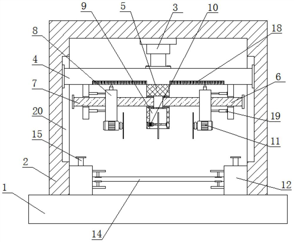
[0029] refer to Figure 1-4 , a synchronous multi-knife fixed-distance cutting device for steel pipes, including a base 1, the top of the base 1 is fixedly connected with a fixed frame 2, the top inner wall of the fixed frame 2 is fixedly connected with a top cylinder 3, and the output shaft of the top cylinder 3 is fixedly connected with a sliding plate 4, the bottom of the sliding plate 4 is fixedly connected with a fixed plate 5, and the bottom of the sliding plate 4 is symmetrically fixedly connected with two vertical plates 6, and one side of each vertical plate 6 is rotatably connected with a screw rod 7, and one end of the screw rod 7 through the fixed plate, and bearings are arranged on both sides of the fixed plate, the end of the screw rod is fixed at the center of the bearing, the other end of the screw rod 7 passes through the vertical plate, and is fixedly connected with a knob, and each screw rod 7 also runs through a Moving plate 8, in order to balance and stabi...

Embodiment 2

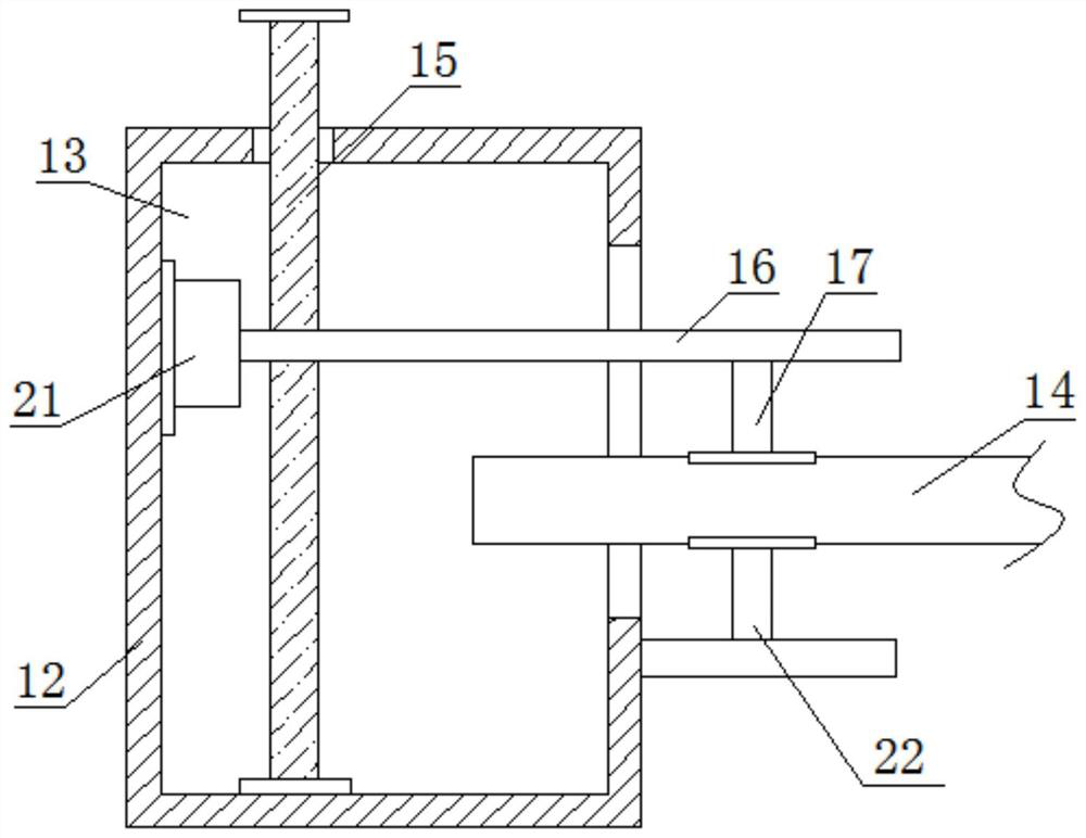
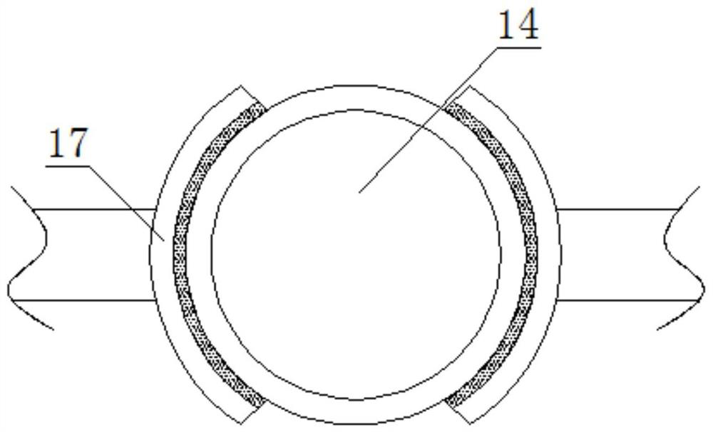
[0034] In the present invention, the clamping assembly includes a threaded shaft 15 that is rotatably connected to the inner wall of the bottom of the fixed chamber 13. The top end of the threaded shaft 15 extends above the top of the fixed base 12 and is fixedly connected with a handle. The threaded shaft 15 is threaded with a threaded plate 16. The sides of the two fixed seats 12 close to each other are fixedly connected with the support plate 22, one side of the threaded plate 16 extends to one side of the fixed seat 12, and the sides of the threaded plate 16 and the support plate 22 close to each other are fixed An arc splint 17 is connected, and the sides of the two arc splints 17 close to each other are closely attached to the top and bottom of the steel pipe body 14, and the threaded plate 16 can drive the arc on the threaded plate 16 through the rotation of the threaded shaft 15. Clamping plate 17 moves downwards, and then can make two arc-shaped splints 17 clamp and fi...


PUM


Abstract

The invention discloses a synchronous multi-cutter fixed-distance cutting device for a steel pipe. According to the cutting device, an output shaft of a top air cylinder is fixedly connected with a sliding plate, wherein the bottom of the sliding plate is fixedly connected with a fixed plate, the bottom of the sliding plate is symmetrically and fixedly connected with two vertical plates, threadedholes are formed in the centers of the vertical plates, a screw rod penetrates through each threaded hole, the other end of each screw rod penetrates through the corresponding vertical plate, a mounting groove is formed in the bottom of the fixed plate, a first cutting motor is fixedly connected to the inner wall of one side of the mounting groove, an output shaft of the first cutting motor is fixedly sleeved with a first cutter, second cutting motors are fixedly connected to the bottoms of the two movable plates, and output shafts of the two second cutting motors are in driving connection with second cutters. According to the device, a steel pipe body can be cut into three sections at a time, and the working efficiency is improved.

Description

technical field [0001] The invention relates to the technical field of steel pipe cutting, in particular to a synchronous multi-knife fixed-distance cutting device for steel pipes. Background technique [0002] Cutting is a physical action. Cutting in a narrow sense refers to cutting objects with sharp tools such as knives; cutting in a broad sense refers to using tools, such as machine tools, flames, etc. to break objects under pressure or high temperature. It plays an important role in people's production and life. In the processing and production of steel pipes, it is necessary to cut steel pipes. [0003] The existing cutting of steel pipes is generally performed with a single knife, and the fixed distance is not convenient, and the fixed distance measurement takes a long time, which reduces the work efficiency. Therefore, we propose a steel pipe synchronous multi-knife fixed distance cutting device to solve the problem. the questions raised above. Contents of the inv...

Claims


Application Information

Patent Timeline
IPC IPC(8): B23D21/00B23D19/06B23D33/02
CPCB23D21/00B23D19/04B23D33/02
Inventor 吴国平朱凯孙增勇
Owner YANGZHOU STRVALUE INFORMATION TECH CO LTD
Why Eureka
Try Eureka