
Composite hole laser punching method based on tip bright point guide

A laser drilling and composite hole technology, which is applied in laser welding equipment, welding equipment, metal processing equipment, etc., can solve the problems of difficult center positioning of the tip, unfavorable secondary drilling processing, and finding the tip of the taper hole, etc., to achieve The effect of solving positioning difficulties

Active Publication Date: 2020-10-16
CHANGCHUN UNIV OF SCI & TECH
View PDF13 Cites 2 Cited by
  • Summary
  • Abstract
  • Description
  • Claims
  • Application Information

AI Technical Summary

Problems solved by technology

However, in this method, when the laser goes deep into the pre-indentation taper hole, the inside of the micro-hole cannot be effectively illuminated, and the positioning CCD magnification of the processing device cannot effectively identify the edge of the peripheral hole, the reference cannot be found, and the center of the tip is difficult to locate. Align the tip of the tapered hole for processing; after reducing the magnification, the resolution and positioning accuracy are not enough to find the tip of the tapered hole, and it is not conducive to accurately realize the laser secondary laser marking under the condition of tip alignment when the indenter has a certain tilt deviation Hole processing

Method used


Image

  • Composite hole laser punching method based on tip bright point guide

Examples


Embodiment 1

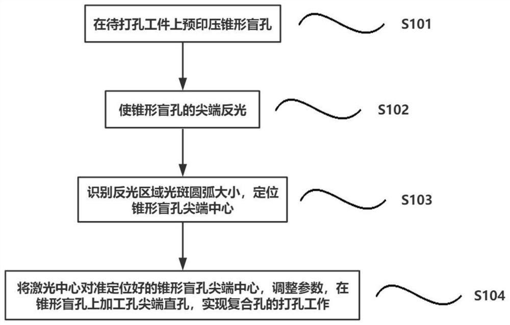
[0020] as attached figure 1 As shown, an embodiment of the present invention provides a laser drilling method for composite holes based on tip bright spot guidance, and the laser drilling method for composite holes includes the following steps:

[0021] S101, using a diamond-made conical indenter to press the metal sheet to form a tapered blind hole on the metal sheet; the tapered blind hole is also called a quasi-preformed tapered hole;

[0022] S102, irradiating the tapered blind hole with ordinary lighting light, so that the tip of the tapered blind hole reflects light;

[0023] S103, according to the image processing function of the positioning CCD, through high-precision contour extraction, arc fitting, and center extraction image processing algorithms, identify the arc size of the light spot in the reflective area, and locate the geometric center of the light spot; the geometric center of the light spot is is the tip center of the tapered blind hole;

[0024] S104, ali...

Embodiment 2

[0027] as attached figure 1 As shown, an embodiment of the present invention provides a laser drilling method for composite holes based on tip bright spot guidance, and the laser drilling method for composite holes includes the following steps:

[0028] S101, using a sapphire conical indenter to press the metal sheet to form a tapered blind hole on the metal sheet; the tapered blind hole is also called a quasi-preformed tapered hole;

[0029] S102, irradiating the tapered blind hole with ordinary lighting light, so that the tip of the tapered blind hole reflects light;

[0030] S103, according to the image processing function of the positioning CCD, through high-precision contour extraction, arc fitting, and center extraction image processing algorithms, identify the arc size of the light spot in the reflective area, and locate the geometric center of the light spot; the geometric center of the light spot is is the tip center of the tapered blind hole;

[0031] S104, align t...

Embodiment 3

[0034] as attached figure 1 As shown, an embodiment of the present invention provides a laser drilling method for composite holes based on tip bright spot guidance, and the laser drilling method for composite holes includes the following steps:

[0035] S101, using a diamond-made conical indenter to press the steel plate to form a tapered blind hole on the steel plate; the tapered blind hole is also called a quasi-preformed tapered hole;

[0036] S102, irradiating the tapered blind hole with ordinary lighting light, so that the tip of the tapered blind hole reflects light;

[0037] S103, according to the image processing function of the positioning CCD, through high-precision contour extraction, arc fitting, and center extraction image processing algorithms, identify the arc size of the light spot in the reflective area, and locate the geometric center of the light spot; the geometric center of the light spot is is the tip center of the tapered blind hole;

[0038] S104, ali...


PUM


Abstract

The invention is applicable to the technical field of composite punching, and provides a composite hole laser punching method based on tip bright point guide. The composite hole laser punching methodbased on tip bright point guide comprises the following steps that a conical blind hole is printed and pressed on a workpiece to be punched; the tip of the conical blind hole reflects light, the sizeof an arc of a light reflecting area light spot can be recognized, and the geometric center of the light spot can be positioned; the geometric center of the light spot is the tip center of the conicalblind hole; and the laser center is aligned with the tip center of the positioned conical blind hole, parameters are adjusted, a hole tip blind hole is machined in the conical blind hole, and punching work of a composite hole can be achieved. The bright point guide effect of the conical blind hole tip is used for positioning, the tip blind hole is machined in the tip center, the needed compositehole is obtained, the problems that during composite hole laser punching, the conical hole tip is difficult to position, and the composite hole punching cannot be precisely carried out can be effectively solved, and the advantages of being convenient, rapid, and accurate are achieved.

Description

technical field [0001] The invention belongs to the technical field of composite drilling, and in particular relates to a laser drilling method for composite holes guided by point bright spots. Background technique [0002] Laser drilling is the use of high-power-density laser beams to irradiate the processed material, so that the material is quickly heated to the vaporization temperature, and evaporates to form holes. Laser drilling is the earliest practical laser processing technology, and it is also one of the main application fields of laser processing. It is classified as laser removal in laser processing, also called evaporation processing. [0003] Although the laser drilling technology has many advantages, there are still technical difficulties for micro-holes with a large depth-to-diameter ratio, especially the micro-composite hole shape of tapered holes and pointed straight holes. The existing technology is to use a conical indenter to print a tapered hole, and t...

Claims


Application Information

Patent Timeline
Patent Type & Authority Applications(China)
IPC IPC(8): B23K26/382B23K26/70
CPCB23K26/382B23K26/702
Inventor 石广丰于占江许金凯张景然李俊烨史国权赵伟宏
Owner CHANGCHUN UNIV OF SCI & TECH
Learn More