
Multifunctional hydraulic hoisting rescue equipment

A multi-functional, hydraulic technology, applied in the direction of equipment fixed on the vehicle, railway car body parts, transportation and packaging, etc., can solve the problems of equipment cannot be laid, affect rescue, complicated installation process, etc., to ensure operational safety and safety. Reliability, simple and fast installation, convenient and flexible operation

Pending Publication Date: 2020-10-16
吉林市祥隆铁路救援技术开发有限公司 +1
View PDF0 Cites 0 Cited by
  • Summary
  • Abstract
  • Description
  • Claims
  • Application Information

AI Technical Summary

Problems solved by technology

The installation process of the existing straight-top and lateral-moving double-rail rescue device is complicated, and the equipment is easily affected by the terrain during the laying process, resulting in uneven laying or ground subsidence, which leads to the phenomenon of vehicle slipping during the lateral movement and the expansion of the accident; at the same time, the existing lifting The single traversing distance of the equipment is short, and the wheelset of the locomotive will be deeply trapped between the two sleepers after the rolling stock is off-line, which will cause the lifting point to be too low and the equipment cannot be laid, which will affect the rescue
At the same time, the existing hydraulic rescue equipment does not have a hydraulic lock and the oil return pipe leaks outside. Outdoor operations can easily cause the oil return pipe to collide or break, posing a great safety hazard
At present, the lower parts of Harmony electric locomotives in operation in China are all equipped with drawbars, which cannot be used for top-up rescue. Rescue using a crane must dismantle the power grid, which is a large and cumbersome operation.

Method used


Image

  • Multifunctional hydraulic hoisting rescue equipment
  • Multifunctional hydraulic hoisting rescue equipment
  • Multifunctional hydraulic hoisting rescue equipment

Examples


Embodiment

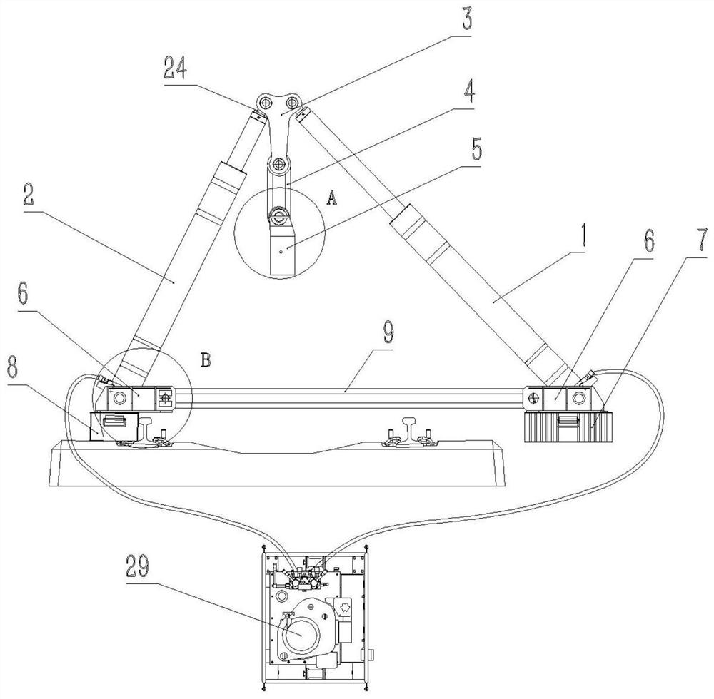
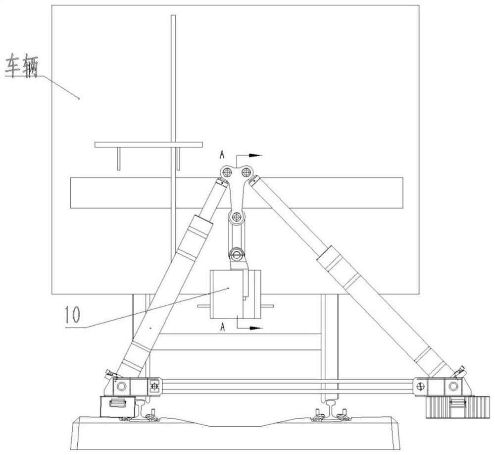
[0036] Such as figure 2As shown, the hook device 5 is installed, and the hook device 5 can be directly slid sideways into the coupler body 10 during installation, and the side of the hook device 5 containing the iron stopper 12 is inserted into the square hole in the coupler body 10 That's it. Install the equipment according to the off-line direction of the car body. If the car body is off-line to the right when facing the direction of the coupler, lay the base fastener beam 8 on the outside of the left rail, and fix the oil cylinder base 6 above the base fastener beam 8. The base support pad 7 is laid on the outside of the side rail, and the oil cylinder base 6 is fixedly installed above the base support pad 7. The two oil cylinder bases 6 are connected by the base connecting rope 9 and the base pin 14, and the proper position is adjusted. The base pin 14 Rotate 90° after piercing into the base of the oil cylinder to prevent it from coming out. Hinge the two single-stage o...


PUM


Abstract

The invention relates to multifunctional hydraulic hoisting rescue equipment which structurally comprises a first single-stage oil cylinder, a second single-stage oil cylinder, an oil cylinder pickaxecap, a T-shaped hanging ring, an upper hanging rope and a hanging hook device and further comprises an oil cylinder base coupling assembly. The bottom of the first single-stage oil cylinder and the bottom of the second single-stage oil cylinder are hinged to the oil cylinder base coupling assembly, the tops of the two single-stage oil cylinders are fixedly connected through the oil cylinder pickaxe cap and then hinged to the T-shaped hanging ring, and the T-shaped hanging ring, the upper hanging rope and the hanging hook device are hinged in sequence. The suspension hook device special for hoisting is arranged below the upper hanging rope, and an stop iron is arranged on the suspension hook device and can bear huge hoisting force after being matched with a square hole in a coupler body; an oil return pipe is arranged in each single-stage oil cylinder, and a hydraulic lock is arranged at the bottom; meanwhile, the two potential safety hazards of rope breakage of existing rescue equipment and breakage of an external oil return pipe of the oil cylinder are avoided, and the multifunctional hydraulic hoisting rescue equipment has the advantages of being reasonable in structure, large in rerailing distance, easy, convenient and efficient to install, not limited by terrains and the like.

Description

technical field [0001] The invention relates to the field of railway rescue equipment, in particular to multifunctional hydraulic lifting rescue equipment. Background technique [0002] A railway traffic accident is a vicious accident that disrupts the normal order of railway transportation. The traditional recovery and rescue method is to install a recovery and rescue device (including hydraulic cylinders, traversing trolleys, etc.) Carry out lifting and traversing operations for retracking. The installation process of the existing straight-top and lateral-moving double-rail rescue device is complicated, and the equipment is easily affected by the terrain during the laying process, resulting in uneven laying or ground subsidence, which leads to the phenomenon of vehicle slipping during the lateral movement and the expansion of the accident; at the same time, the existing lifting The single traversing distance of the equipment is short, and the wheelset of the locomotive wi...

Claims


Application Information

Patent Timeline
IPC IPC(8): B61K5/02
CPCB61K5/02
Inventor 何刚张曦李相家
Owner 吉林市祥隆铁路救援技术开发有限公司
Learn More