Large-plane vapor chamber of composite wick

A liquid absorbing core and soaking plate technology, which is applied in indirect heat exchangers, heat exchange equipment, lighting and heating equipment, etc., can solve the problems of poor heat transfer performance, insufficient steam flow space, and insufficient structural strength.

Pending Publication Date: 2020-10-16
WUXI JONES TECH +3
View PDF0 Cites 4 Cited by
  • Summary
  • Abstract
  • Description
  • Claims
  • Application Information

AI Technical Summary

Problems solved by technology

The vapor chamber of the present invention adopts composite liquid-absorbent cores of different liquid-absorbent core materials and structural forms, cooperates with the evaporation zone and condensation zone of the vapor chamber, and can effectively solve the problem of insufficient steam flow space in the ultra-thin large-plane vapor chamber. In order to solve the problems of poor heat transfer performance and insufficient structural strength, the invention optimizes the design of the liquid-absorbing core structure and support structure of the vapor chamber, which maximizes the steam space and ensures the overall structural strength and uniformity of the vapor chamber. Temperament
This invention is especially suitable for large flat soaking plates with an area larger than 40mm*40mm

Method used


Image

  • Large-plane vapor chamber of composite wick
  • Large-plane vapor chamber of composite wick
  • Large-plane vapor chamber of composite wick

Examples


Embodiment 1

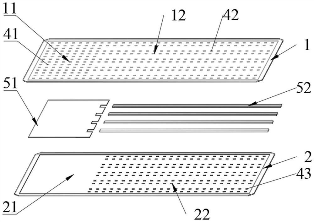
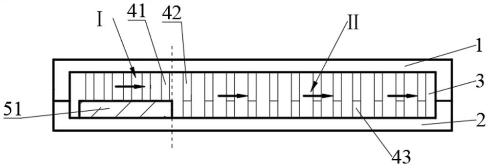
[0029] A large flat vapor chamber of a composite liquid-absorbing core, comprising an upper cover plate 1 and a lower cover plate 2 that are sealed and connected around the periphery to form a sealed working medium cavity 3, the sealed working medium cavity 3 is in a vacuum state, and is filled with liquid Working medium, the upper cover plate 1 is provided with a first area 11 and a second area 12, wherein the first area 11 is near the evaporation end, and is provided with a number of densely arranged first support columns 41, and the second area 12. A number of sparsely arranged second support pillars 42 are provided, wherein a second liquid-absorbing core 52 is placed in the gap between the second support pillars 42;

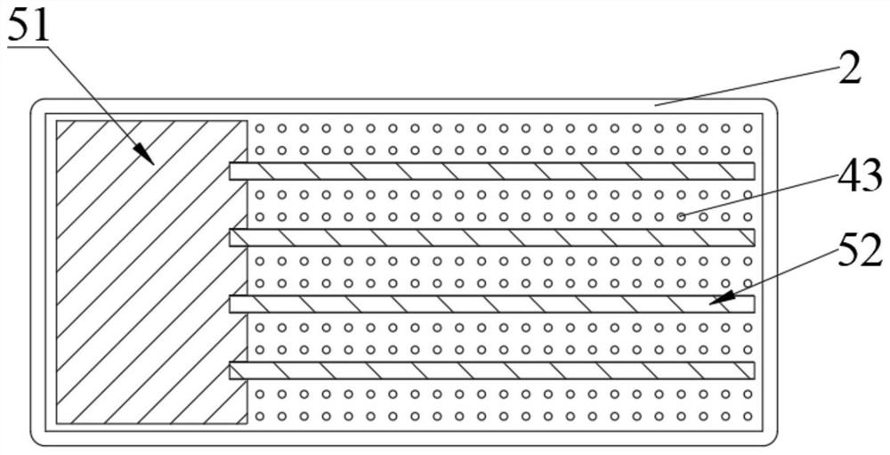
[0030] The lower cover plate 2 is provided with a third area 21 and a fourth area 22, wherein the size of the third area 21 corresponds to the first area 11, and is used to place the first liquid-absorbent core 51; the size of the fourth area 22 Corresponding...

Embodiment 2

[0038] A large flat vapor chamber of a composite liquid-absorbing core, comprising an upper cover plate 1 and a lower cover plate 2 that are sealed and connected around the periphery to form a sealed working medium cavity 3, the sealed working medium cavity 3 is in a vacuum state, and is filled with liquid Working medium, the upper cover plate 1 is provided with a first area 11 and a second area 12, wherein the first area 11 is near the evaporation end, and is provided with a number of densely arranged first support columns 41, and the second area 12. A number of sparsely arranged second support pillars 42 are provided, wherein a second liquid-absorbing core 52 is placed in the gap between the second support pillars 42;

[0039] The lower cover plate 2 is provided with a third area 21 and a fourth area 22, wherein the size of the third area 21 corresponds to the first area 11, and is used to place the first liquid-absorbent core 51; the size of the fourth area 22 Corresponding...


PUM


Abstract

The invention relates to a large-plane vapor chamber of a composite wick. The large-plane vapor chamber comprises an upper cover plate and a lower cover plate, wherein the edges of the upper cover plate and the lower cover plate are connected in a sealed mode to form a sealed working medium cavity. The sealed working medium cavity is in a vacuum state and is filled with a liquid working medium. The upper cover plate is provided with a first area and a second area. The first area is close to an evaporation end and is provided with a plurality of first supporting columns which are densely distributed. The second area is provided with a plurality of second supporting columns which are distributed sparsely. Second wicks are arranged in the gaps between the second supporting columns. The lowercover plate is provided with a third area and a fourth area. The dimension of the third area corresponds to that of the first area, and the third area is used for storing first wicks. The dimension ofthe fourth area corresponds to that of the second area, the fourth area is provided with third supporting columns which are distributed sparsely, and the number and distribution mode of the third supporting columns correspond to those of the second supporting columns. By means of the large-plane vapor chamber, the problems that the flowing space of vapor in large-plane vapor chambers is not enough, the heat transfer performance is poor, and the structural strength is poor can be solved.

Description

technical field [0001] The invention belongs to the technical field of hot plate design and manufacture, and in particular relates to a large-plane soaking plate with a composite liquid-absorbing core. Background technique [0002] At present, various structural forms of the vapor chamber have been proposed. With the development of the vapor chamber towards the trend of large plane and ultra-thin, it is necessary to comprehensively consider various design problems. During the design process, there are usually the following problems: or insufficient steam flow space, or weak capillary force of the liquid-absorbing core, or insufficient overall structural strength, etc. Contents of the invention [0003] The technical problem to be solved by the present invention is to provide a large-plane vapor chamber for a composite liquid-absorbing core in view of the above-mentioned deficiencies in the prior art. The vapor chamber of the present invention adopts composite liquid-abso...

Claims


Application Information

Patent Timeline
Patent Type & Authority Applications(China)
IPC IPC(8): F28D15/04F28F21/08
CPCF28D15/0233F28D15/0283F28D15/046F28F21/081F28F21/089
Inventor 陈曲吴晓宁唐文军胡循亮唐黎何阳
Owner WUXI JONES TECH
Why Eureka
Try Eureka