
Manufacturing method of a bus bar using Friction Stir Welding

A technology of friction stir welding and manufacturing method, which is applied in the direction of manufacturing tools, cable/conductor manufacturing, welding equipment, etc., which can solve the problems of increased maintenance costs, poor combination of aluminum and copper, and unreliability, so as to achieve simple manufacturing process and reduce manufacturing cost. The effect of low cost and strong bonding

Inactive Publication Date: 2020-10-16
阿发屋株式会社
View PDF11 Cites 0 Cited by
  • Summary
  • Abstract
  • Description
  • Claims
  • Application Information

AI Technical Summary

Problems solved by technology

[0006] As mentioned above, in the past, bus bars were usually made of copper or aluminum raw materials. However, copper is expensive and heavy in terms of characteristics, so there is a possibility of causing problems in the durability of the product.
[0007] On the contrary, aluminum, which is an inexpensive raw material, needs to have a volume more than twice that of copper because its electrical conductivity is lower than that of copper raw material. Otherwise, heat will be generated when electricity is turned on, so there will be a problem that a cooler needs to be installed according to the usage environment. In addition, there is a problem that it is not suitable for heavy-duty electrical equipment or equipment with a capacity above that due to the high possibility of melting the aluminum material with a low melting point due to the possibility of arcing that may be generated when energized.
[0008] In addition, as mentioned above, in the case of conventional composite metal bus bars, failure to bond aluminum and copper to each other or bonding between aluminum and copper is often not reliable, so there are cases where the bonded part is damaged due to external impact or the like. The problem of cracking, and thus, there is a disadvantage that the strengthening of the bonding force between aluminum and copper leads to a complicated manufacturing process of the bus bar or an increase in maintenance costs

Method used


Image

  • Manufacturing method of a bus bar using Friction Stir Welding
  • Manufacturing method of a bus bar using Friction Stir Welding
  • Manufacturing method of a bus bar using Friction Stir Welding

Examples


Embodiment Construction

[0034] Hereinafter, embodiments of the present invention will be described in detail with reference to the accompanying drawings so that those skilled in the art can easily implement the present invention. However, the description about the present invention is merely an example for structural or functional illustration, and therefore, the scope of rights of the present invention should not be construed as being limited by the examples described herein. That is, the embodiments can be modified variously and have various forms, and therefore, the scope of rights of the present invention should be understood as including equivalents capable of realizing technical ideas. In addition, as far as the purpose or effect suggested in the present invention is concerned, it does not mean that the specific embodiment needs to include all of them or only include that effect. Therefore, it should not be understood that the scope of rights of the present invention is limited by the specific e...


PUM


Abstract

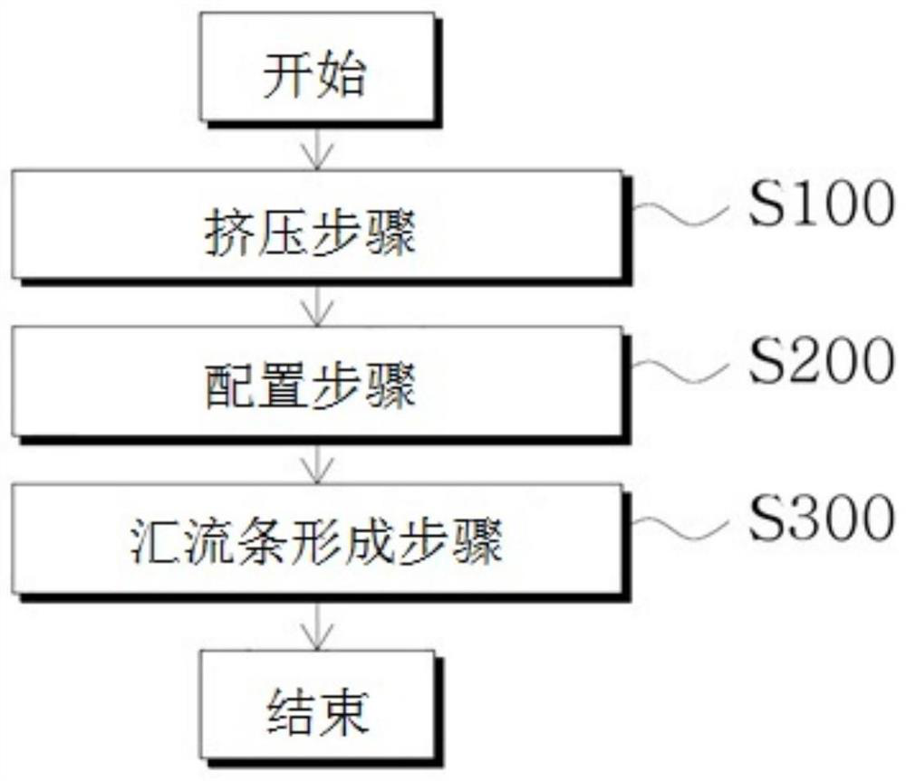
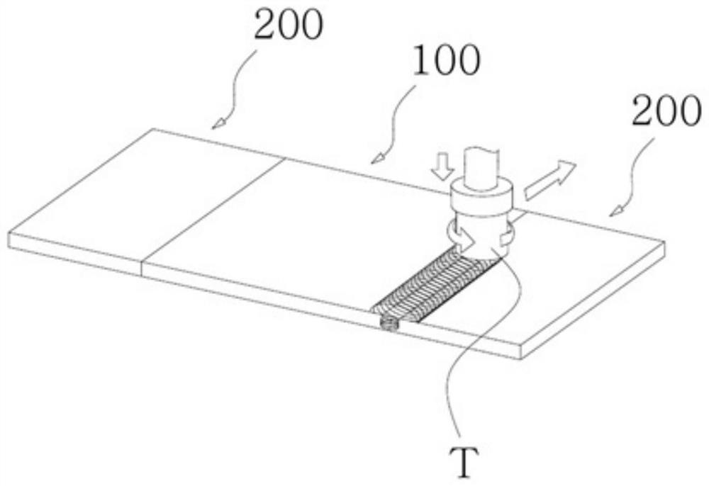
The present invention relates to a method for manufacturing a bus bar, which may be simply manufactured by performing friction stir welding on aluminum and copper. The method comprises: a pressing step of pressing one first conductor and two second conductors into a rectangular shape, respectively; a disposing step of disposing the second conductors at both ends of the first conductor; and a bus bar forming step of forming a bus bar by performing friction stir welding on the gap between the first conductor and the second conductors. The first conductor is aluminum and the second conductor is copper.

Description

technical field [0001] The present invention relates to a method of manufacturing a bus bar by friction stir welding, and more particularly, to a method of manufacturing a bus bar by friction stir welding of aluminum and copper to easily manufacture a bus bar. Background technique [0002] Bus bar (Bus bar) is a medium for transmitting electric energy. In the past, cables were mainly used, but bus bars are often used as a substitute for cables due to their many advantages. [0003] From the structural comparison of bus bars and cables, we can see that they are similar in that they both have conductors and insulators, but the biggest advantage of bus bars is that they can transmit more electrical energy with the same volume of conductors. Therefore, as the advantages of bus bars in large-capacity power distribution systems are known, their use is rapidly increasing, and compared with the past, large buildings, large factories, power plants, subways, etc. that require large-ca...

Claims


Application Information

Patent Timeline
Patent Type & Authority Applications(China)
IPC IPC(8): H01R43/02H01B13/00
CPCH01B13/00H01R4/625H01R43/02B23K20/127B23K20/2275H01B1/02H01B5/02H01B13/0016H01B13/0036
Inventor 金明壎徐宗德
Owner 阿发屋株式会社
Learn More