
Recyclable air purification device for coal-fired thermal power plant

A technology for thermal power plants and purification devices, applied in the field of purification devices and recyclable air purification devices, which can solve the problems of waste of reaction liquid, insufficient reaction, inconvenient collection and cleaning of smoke and fixed impurities, etc.

Pending Publication Date: 2020-10-20
高心成
View PDF8 Cites 1 Cited by
  • Summary
  • Abstract
  • Description
  • Claims
  • Application Information

AI Technical Summary

Problems solved by technology

[0002] Nowadays, there are still thermal power plants in many places, and thermal power plants use coal-fired power generation. When coal-fired power generation is performed, the exhaust gas generally contains acid gases, smoke and solid impurities, which pollute the air.
[0003] Existing recyclable air purification devices used in coal-fired thermal power plants generally use simple spraying to spray alkaline liquid on flue gas to reduce pollution, and process acid gas, smoke and solid impurities. During the use of the treatment method, it was found that the reaction liquid may not fully react with the flue gas after spraying, resulting in a large amount of waste of the reaction liquid, and the dust and fixed impurities after spraying are not easy to collect and clean. Therefore, we designed a A recyclable air purification device for coal-fired thermal power plants

Method used


Image

  • Recyclable air purification device for coal-fired thermal power plant
  • Recyclable air purification device for coal-fired thermal power plant
  • Recyclable air purification device for coal-fired thermal power plant

Examples


Embodiment Construction

[0025] The following will clearly and completely describe the technical solutions in the embodiments of the present invention with reference to the accompanying drawings in the embodiments of the present invention. Obviously, the described embodiments are only some, not all, embodiments of the present invention. Based on the embodiments of the present invention, all other embodiments obtained by persons of ordinary skill in the art without making creative efforts belong to the protection scope of the present invention.

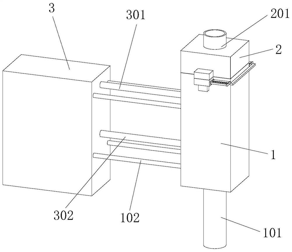
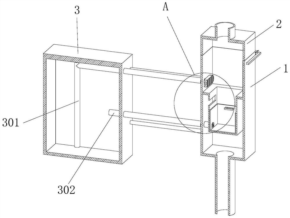
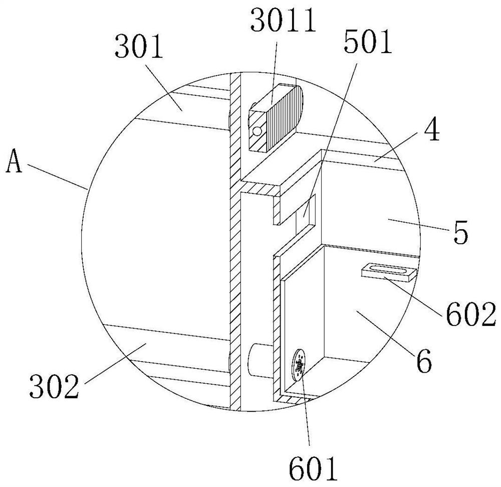
[0026] see Figure 1-6 As shown, a recyclable air purification device for a coal-fired thermal power plant includes a purification device main body 1, the bottom of the purification device main body 1 is fixedly connected with an air intake pipe 101, and the top of the purification device main body 1 is fixedly installed with a top cover cylinder 2. The top of the top cover tube 2 is fixedly connected with an air outlet pipe 201, and the side wall of the main ...


PUM


Abstract

The invention discloses a recyclable air purification device for a coal-fired thermal power plant. The purification device comprises a purification device main body, wherein an air inlet pipe is fixedat the bottom of the purification device main body; a top cover cylinder is fixedly mounted at the top of the purification device main body; an air outlet pipe is fixed at the top of the top cover cylinder; four groups of supporting columns are fixed on the side wall of the purification device main body; and a water tank main body is fixed to the side, away from the purification device main body,of the supporting column, a water outlet pipeline and a water return pipeline are fixed to the side wall of the water tank main body, a square fixing ring is fixed to the side wall of an inner cavityof the purification device main body, a square barrel is fixed to the bottom of the square fixing ring, and an air inlet groove is formed in the side wall of the square barrel. The purification device has the beneficial effects that when flue gas is exhausted, acid gas in the flue gas can be neutralized, meanwhile, smoke dust and solid impurities are sprayed into a collecting box, so it is guaranteed that the exhausted flue gas is small in pollution, and meanwhile, the smoke dust and the solid impurities in the flue gas are convenient to separate and remove.

Description

technical field [0001] The invention relates to a purification device, in particular to a recyclable air purification device used in a coal-fired thermal power plant, and belongs to the technical field of power plants. Background technique [0002] Nowadays, there are still thermal power plants in many places, and thermal power plants use coal-fired power generation. When coal-fired power generation is performed, the exhaust gas generally contains acid gases, smoke and solid impurities, which pollute the air. [0003] Existing recyclable air purification devices used in coal-fired thermal power plants generally use simple spraying to spray alkaline liquid on flue gas to reduce pollution, and process acid gas, smoke and solid impurities. During the use of the treatment method, it was found that the reaction liquid may not fully react with the flue gas after spraying, so a large amount of reaction liquid was wasted, and the dust and fixed impurities after spraying were not eas...

Claims


Application Information

Patent Timeline
IPC IPC(8): B01D53/78B01D53/40
CPCB01D53/78B01D53/40
Inventor 高心成
Owner 高心成
Learn More