Part fixed clamping device for mechanical arm production

A technology for fixing clamping and parts, applied in workpiece clamping devices, metal processing machinery parts, positioning devices, etc., which can solve the problems of inability to adjust the height and angle of the clamping device, inconvenience, and troublesome operation.

Inactive Publication Date: 2020-10-20
袁高宇
View PDF1 Cites 7 Cited by
  • Summary
  • Abstract
  • Description
  • Claims
  • Application Information

AI Technical Summary

Problems solved by technology

The clamping device in the above patent has the following disadvantages: although the clamping device can be adjusted according to the size of the parts, the operation is cumbersome, and the height and angle of the clamping device cannot be adjusted. It is extremely difficult to drill holes at special angles. convenient

Method used


Image

  • Part fixed clamping device for mechanical arm production
  • Part fixed clamping device for mechanical arm production
  • Part fixed clamping device for mechanical arm production

Examples


Embodiment 1

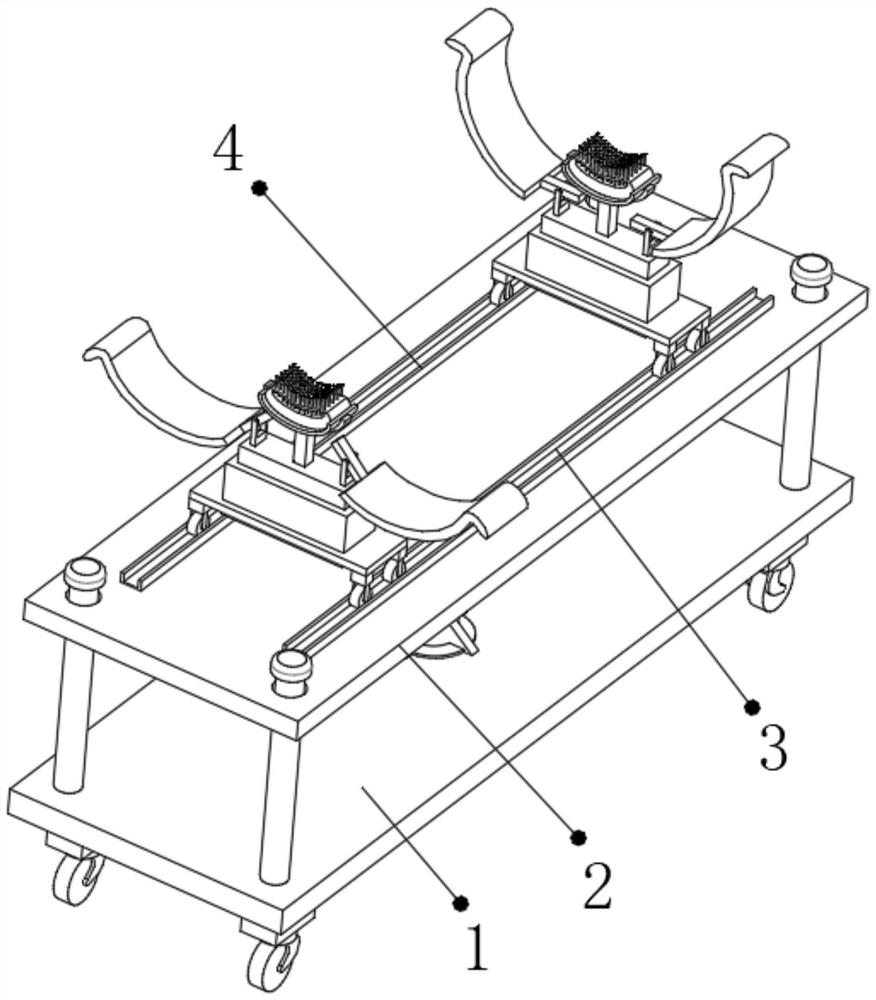
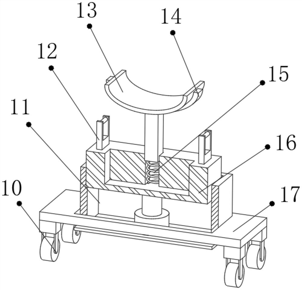
[0029] refer to Figure 1-4 , a kind of fixed and clamping device for mechanical arm production parts, including an operation table 2, the top outer wall of the operation table 2 is connected with a symmetrically distributed first slide rail 3 and a second slide rail 4 by bolts, and the first slide rail 3 Consistent with the size and type of the second slide rail 4, the inner wall of the first slide rail 3 and the second slide rail 4 is rollingly connected to the width adjustment mechanism, and the top outer wall of the width adjustment mechanism is connected with a height adjustment box 11 by bolts, and the height adjustment box 11 There is a cavity on the top outer wall of the cavity, and the inner wall of the cavity is slidably connected with the connection box 16, and the bottom inner wall of the height adjustment box 11 is connected with an electric telescopic rod through bolts, and one end of the output shaft of the electric telescopic rod is connected to the bottom outer...

Embodiment 2

[0033] refer to Figure 5, a kind of mechanical arm production parts fixing and clamping device. Compared with Embodiment 1, the top outer wall of the clamping plate 18 is welded with a bar-shaped magnet block 21 at the corner, and the top outer wall of the clamping plate 18 is welded There are multiple anti-slip protrusions 22.

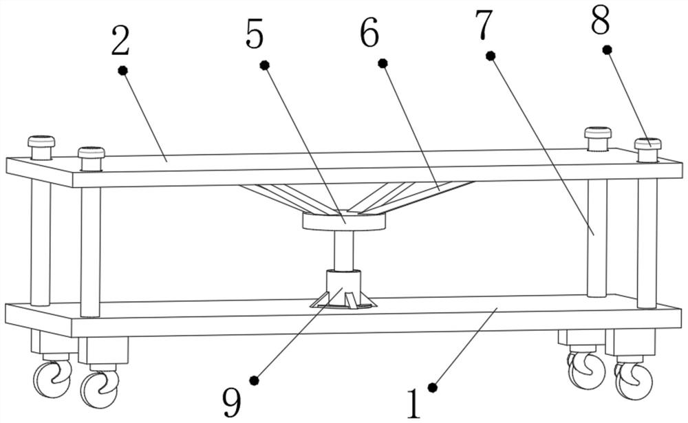
[0034] Working principle: when in use, start the hydraulic lever 9 according to the actual situation of the use environment, and adjust the height of the console 2. There are a pair of height adjustment boxes 11 and other components on the console 2. When the small parts are placed on the clamping frame 13, the clamping plate 18 cannot be pried up due to the small gravity, and the parts are in contact with the clamping column 20, and are absorbed by the ball spring, elastic The pad 19 is depressed inward under the extrusion of gravity, so that the clamping column 20 can wrap the parts and "hold" the parts like a palm, and the large parts can be lift...


PUM


Abstract

The invention discloses a part fixed clamping device for mechanical arm production. The device comprises an operation platform. A first sliding rail and a second sliding rail which are symmetrically distributed are fixedly connected with the outer wall of the top of the operation platform. The first sliding rail and the second sliding rail are the same in size and model. The inner wall of the first sliding rail and the inner wall of the second sliding rail are in rolling connection with a width adjustment mechanism. The outer wall of the top of the width adjustment mechanism is fixedly connected with a height adjustment box. A cavity is formed in the outer wall of the top of the height adjustment box. The inner wall of the cavity is in sliding connection with a connection box. According tothe part fixed clamping device for mechanical arm production, a clamping mechanism can be adjusted in real time according to the size of a part of a mechanical arm, and operation is convenient to carry out; when a small part is placed on a clamping column, the small part is wrapped up by the clamping column like a palm because the elastic effect of gravity extrusion and an elastic pad; and because a large part is high in weight, a clamping plate can be driven by gravity extrusion to overturn to wrap up the big part, and an electric telescopic rod is adjusted.

Description

technical field [0001] The invention relates to the technical field of component fixing and clamping, in particular to a component fixing and clamping device for mechanical arm production. Background technique [0002] In recent years, with the development of robot technology, the application of high-speed, high-precision, high-load-to-weight ratio robot structure has attracted the attention of the industry and aerospace fields, and high-precision robotic arms have emerged. When producing robotic arms, assembly, welding, Drilling, grinding and other operations need to fix the parts of the mechanical arm, and require frequent adjustment and disassembly. Most of the existing fixing and clamping devices cannot be adjusted according to the size of the parts, and the adjustment is difficult. Therefore, a kind of The parts fixing and clamping device used in the production of manipulators solves such problems. [0003] After retrieval, the Chinese patent authorization number is CN...

Claims


Application Information

Patent Timeline
Patent Type & Authority Applications(China)
IPC IPC(8): B25B11/00B23Q3/06B23Q3/04B24B41/06
CPCB23Q3/04B23Q3/062B24B41/06B25B11/00
Inventor 袁高宇
Owner 袁高宇
Why Eureka
Try Eureka