Torque wrench with extremely low counter-acting force to operator

A reaction force and torque wrench technology, applied in the direction of motor tools, manufacturing tools, etc., can solve problems such as acceleration

Active Publication Date: 2020-10-20
SICHUAN UNIV
View PDF18 Cites 1 Cited by
  • Summary
  • Abstract
  • Description
  • Claims
  • Application Information

AI Technical Summary

Problems solved by technology

[0007] The purpose of the present invention is to overcome the shortcomings of acceleration torque in the existing low reaction force electric wrench, and provide a torque wrench that has basically no reaction force on the operator, which can reduce the labor intensity of workers and improve labor efficiency

Method used


Image

  • Torque wrench with extremely low counter-acting force to operator
  • Torque wrench with extremely low counter-acting force to operator
  • Torque wrench with extremely low counter-acting force to operator

Examples


Embodiment Construction

[0024] The present invention will be further described below in conjunction with accompanying drawing, protection scope of the present invention is not limited to the following:

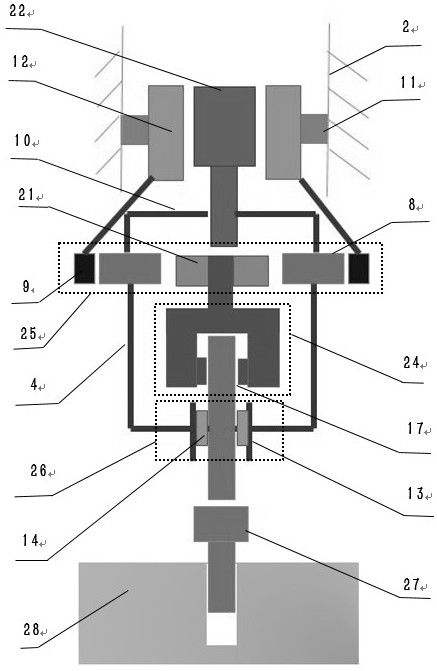
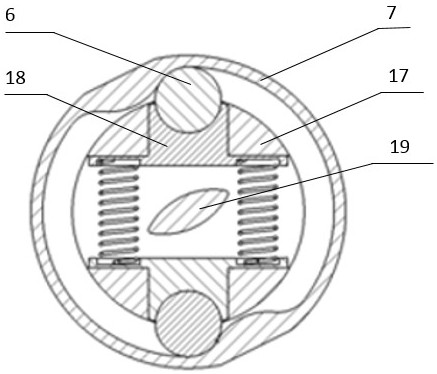
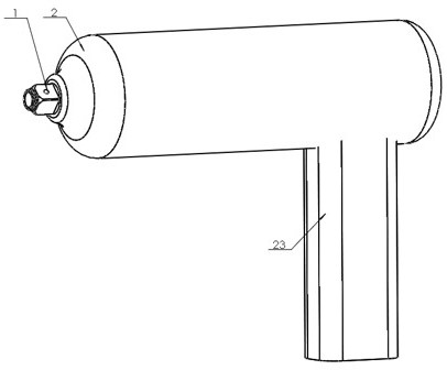
[0025] Such as Figure 1-3 As shown, the present invention provides a torque wrench with extremely low reaction force to the operator, including a power assembly, a transmission assembly and an output assembly. The inner rotor 22 , the motor outer rotor 12 and the casing 2 are assembled through the motor bearing 11 . The transmission assembly includes a planetary gear train 25, a coupling sleeve 4, and a sprag type overrunning clutch 26. The planetary gear train 25 includes a ring gear 9, a planetary gear 8, a sun gear 21, a front planetary carrier 10, a rear planetary carrier 20, and planetary gears. Wheel 8 is connected with front planetary carrier 10, rear planetary carrier 20, sprag type overrunning clutch 26 comprises sprag type overrunning clutch outer ring 13, sprag type overrunning clutch in...


PUM


Abstract

The invention discloses a torque wrench with an extremely low counter-acting force to an operator. The torque wrench comprises a power assembly, a transmission assembly and an output assembly. Duringuse, a part of thread of a screw (27) is screwed into a threaded hole of a workpiece (28), the wrench and a bolt (15) are assembled, and then a power supply switch is turned on to start a fastening operation. By separating a wrench housing (2) from a whole system of torque transfer, the operator needs not to bear the counter-acting force. The torque wrench has the beneficial effects that in the working process, the counter-acting force to the operator is substantially zero, so that the labor intensity can be reduced greatly; the demand of human engineering is met; the unmanned, intelligent, robotized development progress of the torque wrench is accelerated; and the torque wrench is of very high use value.

Description

technical field [0001] The present invention relates to an electric torque transmitting hand-held power tool. Background technique [0002] A torque wrench is a tool used to drive threaded parts such as bolts or screws to rotate and tighten two or more parts. With different power sources and structural features, there are various forms of torque wrenches. From the principle of labor saving, it can be divided into two types, one is the manual booster wrench that adopts the principle of deceleration; the other is the low reaction force wrench that counteracts the reaction force by setting a flywheel and other methods. [0003] Current research on booster wrenches includes Chinese patent CN208713808U, in view of the laborious characteristics of manual wrench tightening operations, double-row transmission gears are used to achieve the effect of deceleration and booster force, and workers are still required to provide tightening force during use. Patents CN208773421U and CN20211...

Claims


Application Information

Patent Timeline
IPC IPC(8): B25B21/02
CPCB25B21/02B25B21/026
Inventor 邬焕欣姚进秦函
Owner SICHUAN UNIV
Why Eureka
Try Eureka