A semi-automatic solder paste printing machine

A solder paste printing machine, semi-automatic technology, applied in printing machines, rotary printing machines, screen printing machines, etc., can solve the problems of different amount of solder paste on PCB pads, high positioning accuracy requirements, and inconsistent pressure, etc. , to achieve the effect of improving solder paste printing quality, improving printing efficiency, and constant pressure

Active Publication Date: 2021-05-04
广州威品技术研发有限公司
View PDF4 Cites 0 Cited by
  • Summary
  • Abstract
  • Description
  • Claims
  • Application Information

AI Technical Summary

Problems solved by technology

[0003] The pressure between the squeegee and the stencil is an important parameter for the quality of solder paste printing. If the pressure is too small, the amount of solder paste on the PCB pad will be insufficient or even the solder paste will be off-printed. If the pressure of the squeegee is too high, the solder paste on the pad will be damaged. If the paste is too thin, it may even damage the stencil. In production, the scraper needs to be repeatedly separated from the stencil and then in contact again. As a result, the pressure between the scraper and the stencil cannot be kept consistent during repeated contact, and there is a certain deviation, which will lead to PCB board The amount of solder paste on the pad is different, so that the quality of subsequent soldering is different, resulting in a decline in product quality. At the same time, the scraper moves back and forth above the steel mesh. After scraping once, it needs to return to its position and spread the solder paste Uniformity, the reciprocating movement of the scraper causes insufficient printing efficiency, and its transmission structure is relatively complicated, which requires high positioning accuracy

Method used


Image

  • A semi-automatic solder paste printing machine
  • A semi-automatic solder paste printing machine
  • A semi-automatic solder paste printing machine

Examples


Embodiment Construction

[0022] The following will clearly and completely describe the technical solutions in the embodiments of the present invention with reference to the accompanying drawings in the embodiments of the present invention. Obviously, the described embodiments are only some, not all, embodiments of the present invention. Based on the embodiments of the present invention, all other embodiments obtained by persons of ordinary skill in the art without making creative efforts belong to the protection scope of the present invention.

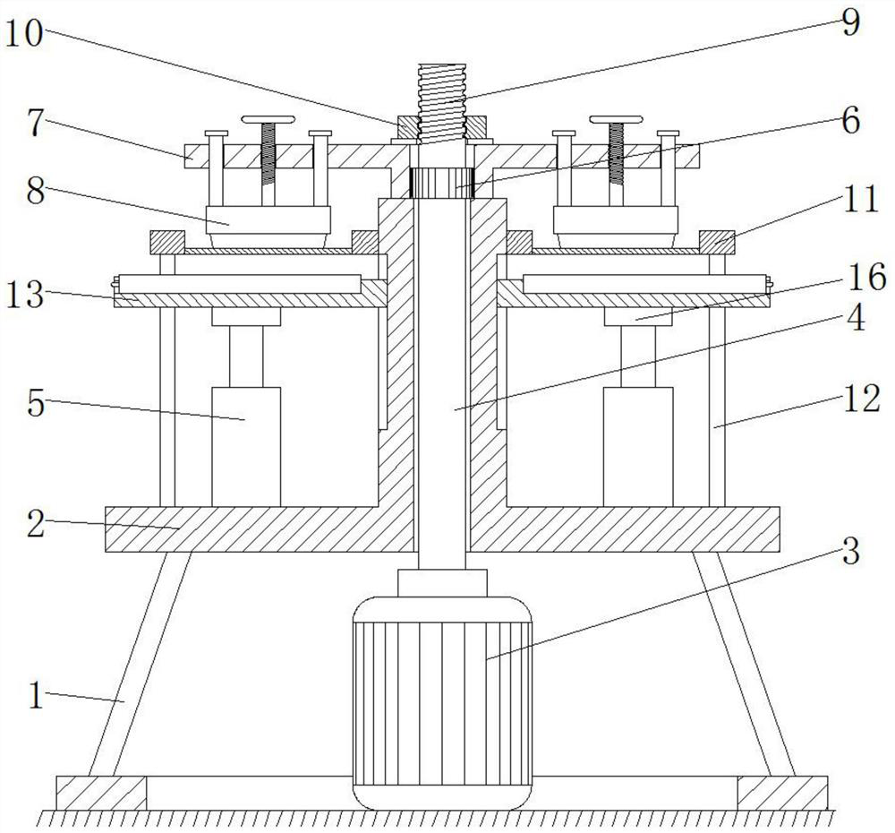
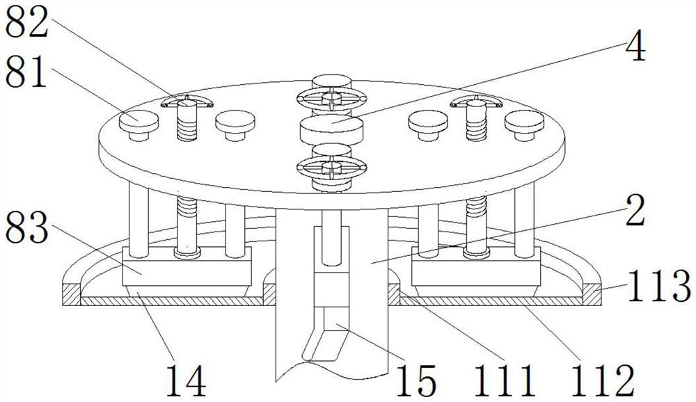
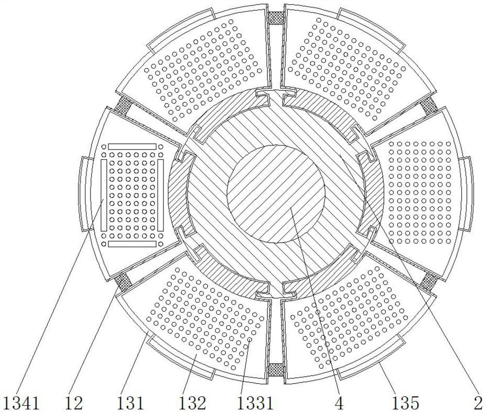
[0023] see Figure 1-5 , a semi-automatic solder paste printing machine, including a support base 1 and an air pump, a rotating support base 2 is fixedly installed on the top of the support base 1, a sliding groove is opened on the rotating support base 2, and a center is movable in the middle of the rotating support base 2 The shaft 4 and the bottom of the central shaft 4 are fixedly connected with a servo motor 3, and the top of the servo motor 3 is fixedly ...


PUM


Abstract

The invention relates to the technical field of printing machines, and discloses a semi-automatic solder paste printing machine, which includes a support base and an air pump. A rotating support base is fixedly installed on the top of the support base, and a sliding groove is opened on the rotation support base. A central shaft is movably socketed in the middle of the rotating support base, and a servo motor is fixedly connected to the bottom of the central shaft. Through the setting of the rotating disk, the fixing device and the screen plate, the scraper moves in a circular motion, so that the contact between the scraper and the annular steel mesh is continuously maintained, thereby ensuring that the pressure between the scraper and the annular steel mesh is kept within a certain range, reducing Fluctuation of pressure ensures that the amount of solder paste passing through the steel mesh is the same, and improves the printing quality of solder paste on PCB pads of the same batch. The PCB board pads on the table are printed, which reduces the time for the scraper to return to the position and improves the printing efficiency.

Description

technical field [0001] The invention relates to the technical field of printing machines, in particular to a semi-automatic solder paste printing machine. Background technique [0002] Surface Mount Technology (SMT for short) has been widely used for its advantages of easy automated production, high assembly density, small size, good high-frequency characteristics, and low cost, and solder paste printing is at the forefront of the SMT process and is the key to the entire SMT process. One of the key processes in the process, the semi-automatic solder paste printing machine has simple structure, convenient operation, and low price, and has been widely used, but the semi-automatic solder paste printing machine still has the following deficiencies, as follows: [0003] The pressure between the squeegee and the stencil is an important parameter for the quality of solder paste printing. If the pressure is too small, the amount of solder paste on the PCB pad will be insufficient or...

Claims


Application Information

Patent Timeline
Patent Type & Authority Patents(China)
IPC IPC(8): B41F15/08B41F15/16B41F15/42B41F15/44
CPCB41F15/0818B41F15/16B41F15/42B41F15/44
Inventor 林瑞娟陈桂珍
Owner 广州威品技术研发有限公司
Why Eureka
Try Eureka