Visual feeding manipulator

A robotic arm and vision technology, applied in the field of automated production, can solve the problems of inconvenient management of trays, large labor costs, and high prices

Pending Publication Date: 2020-10-20
东莞市卡丁精密机械有限公司
View PDF0 Cites 1 Cited by
  • Summary
  • Abstract
  • Description
  • Claims
  • Application Information

AI Technical Summary

Problems solved by technology

[0002] At present, the material trays on the market require personnel to place the knife grains on them, and the position of the blades is well positioned. However, the blades use the 284*385 standard MANZ product turnover trays during the production turnover. This kind of trays cannot be directly It is used on the existing equipment, which requires a lot of extra labor for discharging. It is inconvenient to use two kinds of trays for management. In addition, the price of s

Method used


Image

  • Visual feeding manipulator
  • Visual feeding manipulator
  • Visual feeding manipulator

Examples


Embodiment Construction

[0058] The present invention will be further described below in conjunction with the accompanying drawings and embodiments.

[0059] Please refer to Figure 1-Figure 20 , with vision feeding robotic arm including:

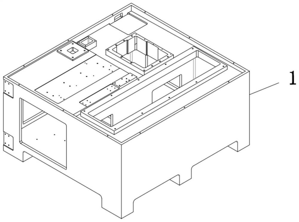
[0060] Installing the base 1, the installing base 1 is used to install each functional part, and is used to fix and connect each functional block;

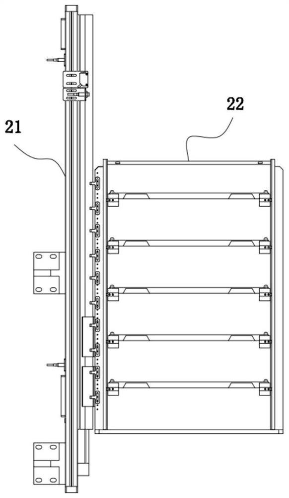
[0061] The feeding table part 2, the feeding table part 2 is installed on one side of the installation base 1, the feeding table part 2 includes a tray moving shaft 21 and a tray supply box 22, and the tray supply box 22 is slidably installed on the moving shaft 21 of the tray;

[0062] Blade turning part 3, described blade turning part 3 is installed on the top side of described installation base 1, and described blade turning part 3 comprises bracket base plate 33, blade turning part 31 and blade corner part 32, and described blade turning part The part 31 and the blade corner part 32 are all installed on the top ...


PUM


Abstract

The invention provides a visual feeding manipulator. The visual feeding manipulator comprises a mounting base, a feed table part, a blade turnover part and a material taking and discharging manipulator part, wherein the feed table part is mounted on one side of the mounting base, and comprises a material tray moving shaft and a material tray supplying box; the material tray supply box is mounted on the material tray moving shaft in a sliding manner; the blade turnover part is mounted on the top side of the mounting base and comprises a bracket base plate, a blade surface turning over part anda blade corner part; and the material taking and discharging manipulator part comprises a Z1 shaft, a C shaft, a vision part, an X1 shaft, a manipulator pressure head and a Y1 shaft. The visual feeding manipulator provided by the invention has the advantages that the visual feeding manipulator can place one thousand or more of processed products, can perform continuous operations all the day, is free from replacement of a material tray, is free from placing positioning on blades, and directly adopts visual positioning, the participation rate of staff can be greatly reduced, the production efficiency can be improved, and the production cost can be reduced.

Description

technical field [0001] The invention relates to the technical field of automated production, in particular to a visual feeding robot arm. Background technique [0002] At present, the material trays on the market require personnel to place the knife grains on them, and the position of the blades is well positioned. However, the blades use the 284*385 standard MANZ product turnover trays during the production turnover. This kind of trays cannot be directly It is used on the existing equipment, which requires a lot of extra labor for discharging. It is inconvenient to use two kinds of trays for management. In addition, the price of standard trays is relatively high, and they are all customized products. Each tray corresponds to one type. Or a blade, and the 284*385 standard MANZ product turnover tray is common to the entire blade production industry, with large output and low price, and all blades can be used for common use. Therefore, the customer hopes that the equipment can...

Claims


Application Information

Patent Timeline
IPC IPC(8): B65G47/90B65G1/04B65G47/248
CPCB65G1/04B65G47/248B65G47/902B65G47/905
Inventor 龙腾
Owner 东莞市卡丁精密机械有限公司
Why Eureka
Try Eureka