A Concrete Inner Vibration Casting Technology

A technology of concrete inside and concrete, applied in construction, foundation structure engineering, sheet pile walls, etc., can solve the problems of non-vertical vibrating rods, slow insertion, poor concrete vibration effect, etc., and achieve the effect of easy bonding and fixing

Active Publication Date: 2021-08-31
莒县玖力建材有限公司
View PDF0 Cites 0 Cited by
  • Summary
  • Abstract
  • Description
  • Claims
  • Application Information

AI Technical Summary

Problems solved by technology

[0003] According to the concrete material and pouring process requirements, the concrete is vibrated. Most of the existing vibrators are artificially controlled vibrating rods. There may be vibration rods that are not vertical when inserted into the concrete, inserted too slowly and pulled out too quickly, and concrete vibrations. Poor practical effect and other problems, it is easy to leave pores in the concrete, and for some construction sites with large pouring area, it is inconvenient to manually control and the work efficiency is low

Method used


Image

  • A Concrete Inner Vibration Casting Technology
  • A Concrete Inner Vibration Casting Technology
  • A Concrete Inner Vibration Casting Technology

Examples


Embodiment 1

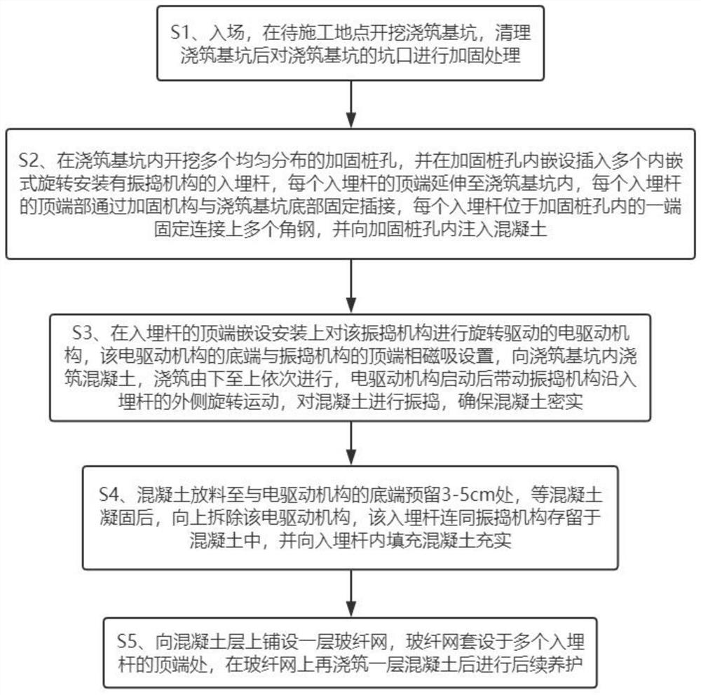
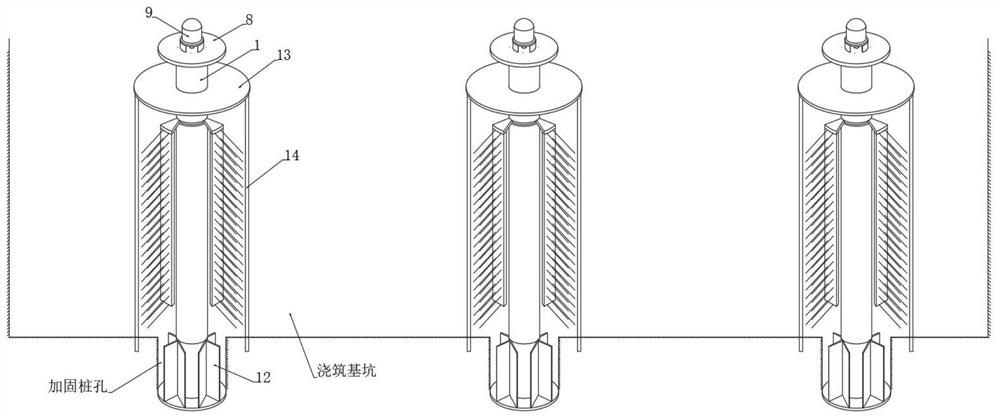
[0041] see Figure 1-2 , a concrete pouring process with internal vibration, the specific pouring steps are as follows:

[0042] S1. Entering the site, excavating and pouring foundation pits at the site to be constructed, and reinforcing the mouth of the pouring foundation pits after cleaning the pouring foundation pits;

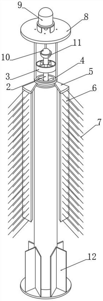
[0043] S2. Excavate a plurality of uniformly distributed reinforcement pile holes in the pouring foundation pit, and insert a plurality of embedded rods 1 with a vibrating mechanism installed in the reinforcement pile holes, and each embedded rod 1 The top end extends into the pouring foundation pit, and the top end of each embedded rod 1 is fixedly inserted into the bottom of the pouring foundation pit through a reinforcement mechanism. One end of each embedded rod 1 located in the reinforcement pile hole is fixedly connected to a plurality of angle steels 12, and Inject concrete into the reinforced pile hole;

[0044] S3. An electric drive mechanism for ...


PUM


Abstract

The invention discloses a concrete internal vibration type pouring process, which belongs to the technical field of concrete pouring. The embedded rod is buried in the pouring foundation pit, and an embedded vibrating mechanism is arranged on the embedded rod. The electric drive mechanism at the top of the buried rod drives the vibrating mechanism to rotate. The vibrating mechanism rotates along the outside of the buried rod to vibrate and exhaust the concrete poured into the foundation pit. After the pouring is completed, the electric drive is removed upwards. Mechanism, fill and pour concrete into the buried rod for enrichment. The buried rod and the vibrating mechanism are reserved in the concrete without pulling out, which can effectively avoid leaving pores in the concrete due to improper pulling up. The buried rod and the vibrating mechanism are reserved in the concrete to reinforce the concrete, so that there is no need to load some reinforcing mechanisms similar to steel bars inside and outside the concrete to improve the overall mechanical strength of the concrete. In addition, there is no need to manually hold the vibrating rod for operation.

Description

technical field [0001] The invention relates to the technical field of concrete pouring, in particular to a concrete internal vibration pouring process. Background technique [0002] With the acceleration of the level of urbanization, more and more buildings and roads are being built in the city, and most of the buildings in residential areas use concrete frame structures, which have good stability and earthquake resistance. , so the concrete needs to be vibrated when pouring concrete to achieve a good stability effect, and the vibrator in the existing equipment has certain disadvantages when it is working. [0003] According to the concrete material and pouring process requirements, the concrete is vibrated. Most of the existing vibrators are artificially controlled vibrating rods. There may be vibration rods that are not vertical when inserted into the concrete, inserted too slowly and pulled out too quickly, and concrete vibrations. Poor practical effect and other proble...

Claims


Application Information

Patent Timeline
Patent Type & Authority Patents(China)
IPC IPC(8): E02D5/34E02D5/48E02D5/72E02D15/04
CPCE02D5/34E02D5/48E02D5/72E02D15/04E02D2250/0023
Inventor 杨盈
Owner 莒县玖力建材有限公司
Why Eureka
Try Eureka