Power turbine inlet guider for combustion drive compressor unit

A technology for compressor units and power turbines, which is applied in the directions of machines/engines, mechanical equipment, engine components, etc., and can solve problems such as large losses, long axial dimensions, and complex structures.

Active Publication Date: 2020-10-20
中船重工龙江广瀚燃气轮机有限公司
View PDF18 Cites 1 Cited by
  • Summary
  • Abstract
  • Description
  • Claims
  • Application Information

AI Technical Summary

Problems solved by technology

[0007] The purpose of the present invention is to solve the problems of complex structure, long

Method used


Image

  • Power turbine inlet guider for combustion drive compressor unit
  • Power turbine inlet guider for combustion drive compressor unit
  • Power turbine inlet guider for combustion drive compressor unit

Examples


specific Embodiment approach 1

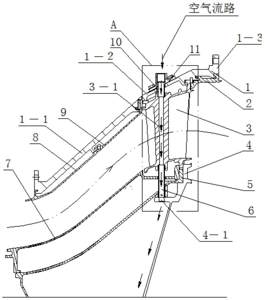
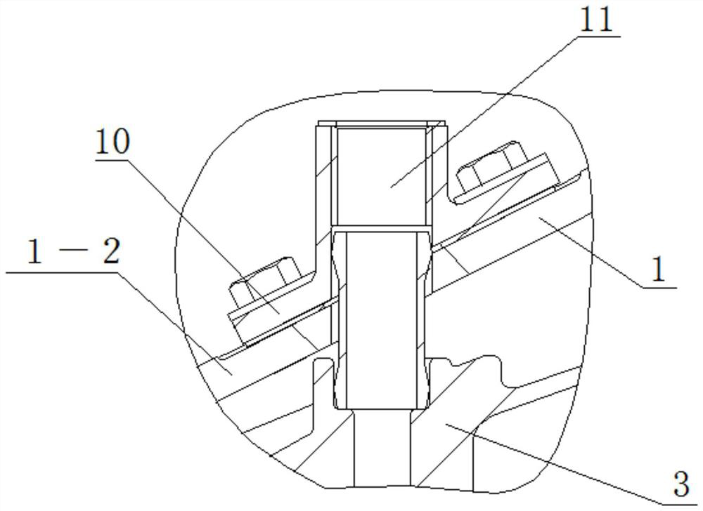
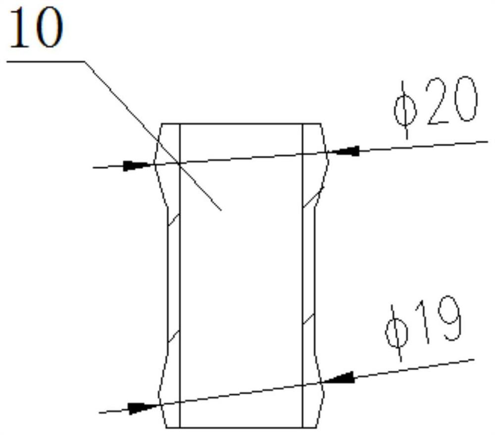
[0026] Specific implementation mode one: combine Figure 1 to Figure 4 Describe this embodiment, a power turbine inlet guide for a combustion drive compressor unit in this embodiment includes a guard ring 2, a guide vane set 3 and a guide vane set pressure ring 4, and it also includes an isolation cover 5, an inner casing 7, The casing 1 and the cooling system, the inner casing 7 is set on the isolation cover 5, the casing 1 is set on the outside of the inner casing 7 and connected to the inner casing 7 through the guide vane group 3, and the lower part of the guide vane group 3 is passed through the guide vane The group pressure ring 4 is press-fitted on the isolation cover 5, the upper part of the guide vane group 3 is press-fitted on the casing 1 through the retaining ring 2, and the cooling system is installed in the casing 1, the guide vane group 3, and the inner cover from top to bottom. On the casing 7 and the isolation cover 5; the casing 1 is a casing with a large mer...

specific Embodiment approach 2

[0028] Specific implementation mode two: combination figure 1 Describe this embodiment, casing 1 of this embodiment comprises diffuser section 1-1, gentle section 1-2 and grommet installation section 1-3, diffuser section 1-1, gentle section 1-2 and grommet installation Segments 1-3 are sequentially connected from left to right and integrated. Such setting can not only reduce the axial dimension of the guide, but also facilitate the installation of the guide vane group and other equipment and parts, avoiding the sudden increase of the expansion angle of the diffuser section, which will cause other existing guide vanes to be damaged. Inconvenience in design, manufacturing, craftsmanship, and assembly caused by the inability to install leaf groups and other components. Other compositions and connections are the same as in the first embodiment.

specific Embodiment approach 3

[0029] Specific implementation mode three: combination figure 1 To describe this embodiment, the included angle between the diffuser section 1 - 1 and the axis in this embodiment is 41°-43°. With such arrangement, the axial dimension of the guide is shortened under the premise of ensuring the connection between the gas generator turbine and the power turbine. Other compositions and connections are the same as those in Embodiment 1 or Embodiment 2.


PUM


Abstract

The invention discloses a power turbine inlet guider for a combustion drive compressor unit, and relates to a power turbine inlet guider. The power turbine inlet guider aims at solving the problems that an existing turbine inlet guider is complex in structure, long in axial size, large in loss and poor in realizability. The power turbine inlet guider is characterized in that an inner housing (7) sleeves an isolation hood (5), a casing (1) is arranged on the outside of the inner housing (7) in a sleeving mode and connected with the inner housing (7) through a guide vane group (3), the guide vane group (3) is pressed on the lower portion of the isolation hood (5) through a guide vane group pressing ring (4), and the guide vane group (3) is pressed on the upper portion of the isolation hood (5) through a retaining ring (2); and a cooling system is sequentially arranged on the casing (1), the guide vane group (3), the inner housing (7) and the isolation hood (5) from top to bottom, the casing (1) is a casing with a large meridian expansion angle, and a flow channel between the casing (1) and the inner housing (7) is S-shaped. The power turbine inlet guider is used for the fuel-driven compressor unit.

Description

technical field [0001] The invention relates to a power turbine inlet guide. In particular, it relates to a power turbine inlet guide used for connecting a gas generator turbine and a power turbine with a large meridional expansion structure for a combustion drive compressor unit, with relatively short axial dimensions and low loss. Background technique [0002] Gas turbines have the characteristics of high power density and rapid response, and are widely used in power generation, mechanical drives and other fields. Modern gas turbines are developing in the direction of high power, high efficiency, and high stability and reliability. High-performance and high-reliability power turbines are an important guarantee for gas turbines' work economy, safety, and function realization. [0003] Gas turbines used in natural gas pipelines to drive compressor units usually adopt a structure with a power turbine. The gas generator turbine speed of this gas turbine is much higher than th...

Claims


Application Information

Patent Timeline
IPC IPC(8): F01D9/04F01D25/14
CPCF01D9/041F01D25/145
Inventor 林枫牛夕莹马涛林洪飞李宗全李国强
Owner 中船重工龙江广瀚燃气轮机有限公司
Why Eureka
Try Eureka