Cooling structure of turbine movable vane of gas turbine

A technology of cooling structure and gas turbine, which is applied to machines/engines, supporting elements of blades, mechanical equipment, etc., can solve the problems of high heat transfer coefficient of blade tip, difficult to arrange cooling structure, large heat transfer coefficient of leading edge, etc.

Active Publication Date: 2020-10-23
浙江燃创透平机械有限公司
View PDF4 Cites 5 Cited by
  • Summary
  • Abstract
  • Description
  • Claims
  • Application Information

AI Technical Summary

Problems solved by technology

For moving blades, this problem is more prominent due to the small diameter of the leading edge, which has a large heat transfer coefficient, making cooling very difficult
At the same time, the leakage flow at the top of the moving blade leads to a generally high heat transfer coefficient at the top of the blade, and due to geometric size and space constraints, it is difficult to arrange a suitable cooling structure on the top of the blade, so the cooling design problem at the top of the moving blade is also more prominent

Method used


Image

  • Cooling structure of turbine movable vane of gas turbine
  • Cooling structure of turbine movable vane of gas turbine
  • Cooling structure of turbine movable vane of gas turbine

Examples


Embodiment Construction

[0048] It should be understood that the specific embodiments described here are only used to explain the present invention, not to limit the present invention.

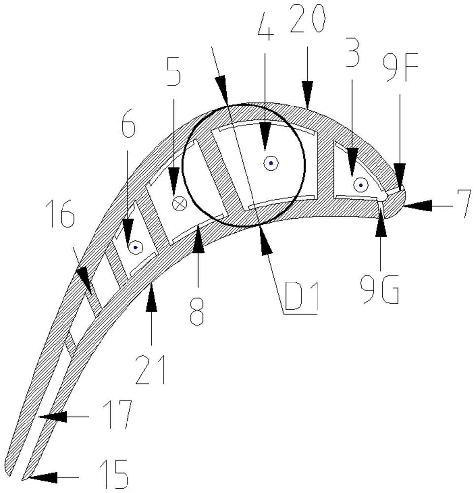
[0049]Below, the present invention will be further described in detail through specific embodiments in conjunction with the accompanying drawings. Wherein, the D1 is the maximum thickness of the airfoil section.

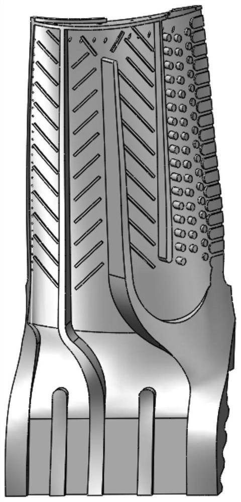
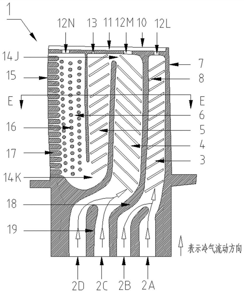
[0050] Such as Figure 1-8 As shown, the present invention provides a cooling structure for the rotor blade of a gas turbine, including four passages arranged in sequence in the blade 1,

[0051] The first channel 3 is adjacent to the leading edge 7 of the blade;

[0052] The second passage 4 is a serpentine passage arranged at an interval of 3 from the first passage;

[0053] The third passage 5 is a serpentine passage arranged at intervals from the second passage 4;

[0054] The fourth channel 6 is a serpentine channel formed with the third channel 5 and the blade trailing edge 15;

[0055] The blade ...


PUM


Abstract

The invention discloses a cooling structure of a turbine movable vane of a gas turbine. The cooling structure comprises four channels sequentially distributed in the vane, a vane top part and a vane bottom part. The first channel is adjacent to the front edge of the vane, the second channel is a serpentine channel spaced from the first channel, the third channel is a serpentine channel spaced fromthe second channel, and the fourth channel is a serpentine channel formed by the third channel and the tail edge of the vane; the vane top part is located at the upper end of the first, second, thirdand fourth channels and is of an incomplete groove structure; and the vane bottom part is located at the lower end of the first, second, third and fourth channels. Compared with the prior art, the front edge of the vane, the vane top part and other parts of a vane body can be fully cooled, the cooling effect is good, and manufacturing is simple.

Description

technical field [0001] The invention relates to the technical field of turbine blades of heavy-duty gas turbines on the ground, and in particular discloses a cooling structure for the turbine blades of a gas turbine with good cooling effect and simple manufacture. Background technique [0002] In order to improve the overall efficiency of the gas turbine, the gas temperature of the turbine is increasing year by year. The current gas inlet temperature is much higher than the withstand temperature of the metal material. Therefore, the cooling design of the turbine blade has become one of the key technologies in the design of the gas turbine. Cool the blade to an acceptable temperature level without exceeding the target value. Among them, the heat transfer coefficient of the leading edge of the blade and its vicinity is very large, which can reach 2 to 4 times the average heat transfer coefficient of the outer surface of the blade. For moving blades, due to the small diameter ...

Claims


Application Information

Patent Timeline
Patent Type & Authority Applications(China)
IPC IPC(8): F01D5/18F01D25/00
CPCF01D5/186F01D25/00Y02T50/60
Inventor 隋永枫王博周灵敏余沛坰谢健初鹏蓝吉兵朱子奇
Owner 浙江燃创透平机械有限公司
Why Eureka
Try Eureka