Cut gas flow-guide device capable of being bidirectionally embedded into internal combustion engine

A technology of a flow guiding device and an internal combustion engine, which is applied in the directions of combustion air/combustion-air treatment, charging system, mechanical equipment, etc., can solve the problems of increased manufacturing cost, difficult assembly, and decline.

Inactive Publication Date: 2020-10-23
王国川
View PDF1 Cites 0 Cited by
  • Summary
  • Abstract
  • Description
  • Claims
  • Application Information

AI Technical Summary

Problems solved by technology

This action has certainly caused the air to be more active, but because of the drop in temperature caused by the rapid passing of the air, the effect of the far-infrared heating by the mesh 11 will be greatly reduced, and even more than figure 1 shown
[0005] As shown in the above two embodiments, it can be realized that its structure is complicated, the manufacturing cost will definitely increase relatively, and the assembly is not easy; what's more, if the component loses the ability to be fixed on the inner wall of the intake pipe due to aging of the component, so that some components If it is sucked into the internal combustion engine, the loss to consumers may not be a small sum

Method used


Image

  • Cut gas flow-guide device capable of being bidirectionally embedded into internal combustion engine
  • Cut gas flow-guide device capable of being bidirectionally embedded into internal combustion engine
  • Cut gas flow-guide device capable of being bidirectionally embedded into internal combustion engine

Examples


Embodiment Construction

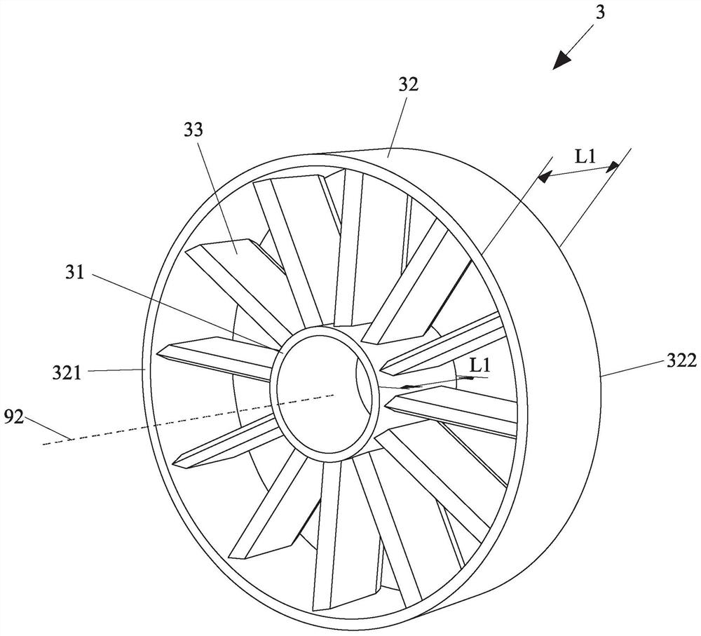
[0026] See Figure 3 to Figure 6 As shown, it is a schematic diagram of the three-dimensional structure, the three-dimensional structure from another perspective, the front view and the rear view of the preferred embodiment of the cutting gas guiding device that can be inserted into the internal combustion engine in two directions according to the present invention. The cutting gas guide device 3 capable of being inserted into the internal combustion engine in two directions according to the present invention includes a core ring structure 31, an outer ring structure 32 and a plurality of guide parts 33. The core ring structure 31 is a hollow cylinder. The outer ring structure 32 and the core ring structure 31 are a hollow cylinder with the same axis 92, and the outer ring structure 32 accommodates the core ring structure 31. The outer ring structure 32 has a first end surface 321 and a first end surface 321. Two end surfaces 322, the first end surface 321 and the second end s...


PUM


Abstract

The invention provides a cut gas flow-guide device capable of being bidirectionally embedded into an internal combustion engine. The cut gas flow-guide device capable of being bidirectionally embeddedinto the internal combustion engine is embedded into the inner wall of a gas inlet pipe of the internal combustion engine in a gas inlet direction. The flow-guide device comprises a core ring structure, an outer ring structure and a plurality of flow-guide parts. The outer ring structure and the core ring structure are a hollow cylinder with the same axis, and the outer ring structure accommodates the core ring structure; the outer ring structure is provided with a first end surface and a second end surface; and a distance is formed between the first end surface and the second end surface. Anaxial surface is defined on each flow-guide part, each axial surface extends to the axis, and a plurality of the axial surfaces are radially arrayed by taking the axis as a center; and each flow-guide part is connected with the core ring structure and the outer ring structure. A structure adjacent to the first end surface and the second end surface, of each flow-guide part, is designed to be in the shape of a triangular prism, so that regardless of which one of the first end surface and the second end surface of the flow-guide device is adjacent to the gas inlet direction, gas can be cut by virtue of the flow-guide parts while entering and the volume of gas entering through atomization can be increased.

Description

Technical field: [0001] The invention relates to a flow guiding device, and more particularly to a cutting gas guiding device that can be inserted into an internal combustion engine in different directions. Background technique: [0002] In modern life, steam and locomotives are indispensable means of transportation. However, the fuel required for power when starting and running the components of steam and locomotives, and the air pollution caused by the exhaust gas discharged, also cause environmental warming. One of the reasons for the phenomenon. The power output of a general vehicle internal combustion engine is almost determined by the amount of air injected into the combustion chamber in a certain proportion. Under different conditions and requirements, the gas has its own optimal gas to fuel ratio. If too much fuel lacks an appropriate ratio Gas cannot be reliably burned, and incomplete combustion produces a large amount of toxic waste gas, causing serious air pollution. ...

Claims


Application Information

Patent Timeline
Patent Type & Authority Applications(China)
IPC IPC(8): F02M29/04F02M35/104
CPCF02M29/04F02M35/104
Inventor 王国川
Owner 王国川
Why Eureka
Try Eureka