
Reinforced structure for built-in circumferential weld of metal corrugated pipe expansion joint

A technology of metal bellows and strengthening structure, which is applied in the direction of expansion compensation device, pipe element, pipe/pipe joint/pipe fitting for pipeline, etc. Working hours, etc.

Pending Publication Date: 2020-10-23
JIANGSU SHUGUANG PRESSURE VESSEL
View PDF0 Cites 0 Cited by
  • Summary
  • Abstract
  • Description
  • Claims
  • Application Information

AI Technical Summary

Problems solved by technology

[0003] The side of the straight pipe of the metal bellows is likely to cause defects such as welding through or collapse of the thinnest straight pipe wall
Although such welding defects can achieve the expected quality through repair welding afterwards, it will significantly increase the production man-hours, thereby increasing the manufacturing cost

Method used


Image

  • Reinforced structure for built-in circumferential weld of metal corrugated pipe expansion joint
  • Reinforced structure for built-in circumferential weld of metal corrugated pipe expansion joint
  • Reinforced structure for built-in circumferential weld of metal corrugated pipe expansion joint

Examples


Embodiment 1

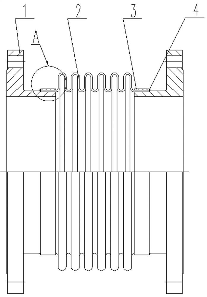
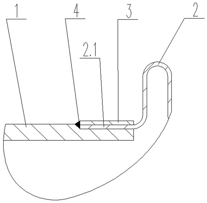
[0021] figure 2 Shown is a schematic diagram of the partial structure of the present invention, and this example is suitable for matching with medium-pressure series expansion joints. The extended end of the connecting pipe 1 shown in the figure is a round pipe with a shoulder, and the matching corrugated pipe 2 is fitted with the extending end of the connecting pipe 1 with the preset straight pipe section 2.1. In order to further strengthen the welding quality of the joint between the straight pipe section 2.1 of the corrugated pipe 2 and the connecting pipe 1, a ferrule 3 is fitted on the outer wall of the straight pipe section 2.1 of the corrugated pipe 2. Since the pressure value of this embodiment belongs to the medium pressure range, the wall thickness of the ferrule 3 is appropriately increased, and the thickness used is 3mm thicker than the wall thickness of the supporting bellows 2 . In order to improve weldability and welding quality, the ferrule 3 is a section of ...

Embodiment 2

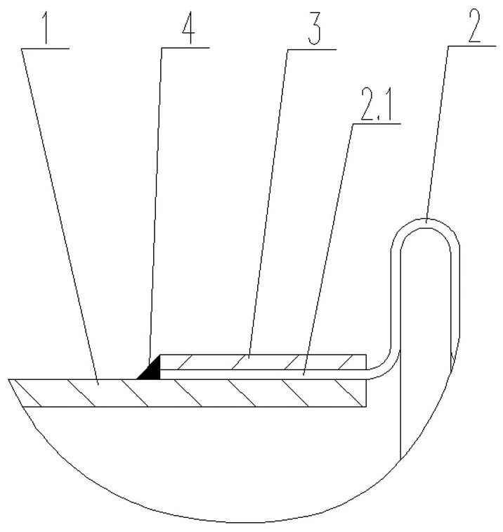
[0023] image 3 The structure shown is the same as figure 2 The main body of the structure shown is the same, only the extension end of the connection pipe 1 is partially improved. In this embodiment, the extension end of the connection pipe 1 is a section of equal-diameter circular pipe, and its function is the same as that of the embodiment 1. This structure is more than figure 2 The structure shown is simpler, especially suitable for low-pressure series expansion joints.

Embodiment 3

[0025] Figure 4 The structure shown is the same as figure 2 The main body of the structure shown is the same, and only the number and position of the supporting ferrules 3 have been partially improved. In this embodiment, a ferrule 3 is fitted on the inner and outer walls of the preset straight pipe section 2.1 of the bellows 2. This double ferrule 3. The structure and function are the same as those of Example 1, but the strength of the formed ring weld 4 is better than that of Example 1. Therefore, this example is especially suitable for supporting high-pressure series expansion joints.


PUM


Abstract

The invention discloses a reinforced structure for a built-in circumferential weld of a metal corrugated pipe expansion joint. The reinforced structure comprises a connecting pipe, a corrugated pipe,hoops and the circumferential weld, wherein circular straight pipe segments are respectively preset in two axial ends of the corrugated pipe; each hoop is a thin-wall circular straight pipe, and is nested with the corresponding straight pipe segment preset in the matched corrugated pipe, and a port to be welded of each hoop is leveled with an outward port of the corresponding straight pipe segmentpreset in the matched corrugated pipe; and the circumferential weld is located at the jointing positions of the hoops, the outward ports of the straight pipe segments of the corrugated pipes and theconnecting pipe to form an overlaid angle direction connecting structure by using the connecting pipe as a liner. According to the reinforced structure disclosed by the invention, the straight pipe segments of the corrugated pipe and the hoops are directly nested on the connecting pipe, formed butt-jointed seams are in the shape of steps, the butt-jointed structure is convenient for implementationof angle direction welding, angle welding is better than flat welding in penetration properties, and the formed circumferential weld is high in connecting strength.

Description

technical field [0001] The invention relates to a welding structure of metal components, in particular, the invention relates to a structure for the built-in girth weld of metal bellows expansion joints, especially a strengthening structure for the built-in girth weld of metal bellows expansion joints . Background technique [0002] During the operation of industrial and civil heat pipe networks, a certain amount of axial thrust and even a small amount of angular displacement will inevitably be generated due to changes in the temperature and pressure of the built-in medium. These objectively existing axial thrust and angular displacement are destructive to the erected thermal pipe network, so necessary technical measures must be taken during engineering design to minimize these destructive effects. The most commonly used technology in engineering is to add expansion joints at the relevant nodes of the heat pipe network, and use the elastic deformation characteristics of the...

Claims


Application Information

Patent Timeline
IPC IPC(8): F16L51/02
CPCF16L51/025F16L51/027
Inventor 游诗青张辉王晓燕
Owner JIANGSU SHUGUANG PRESSURE VESSEL
Learn More