Forced centering device capable of being freely lifted, recycled and capable of achieving integrated operation

A forced centering and free technology, applied in the field of measuring instruments, can solve the problems of unobservable, low precision, low operating efficiency, etc.

Pending Publication Date: 2020-10-23
CHINA CONSTR THIRD ENG BUREAU GRP CO LTD
View PDF0 Cites 1 Cited by
  • Summary
  • Abstract
  • Description
  • Claims
  • Application Information

AI Technical Summary

Problems solved by technology

Setting up the tripod measurement method is to set up the instrument on a wooden tripod, adjust the height of the tripod to carry out centering and leveling, and then carry out rear-view orientation for observation. The site is not convenient to set up instruments and the accuracy is not high), each set of instruments requires at least 2-4 surveyors (many personnel required, high labor costs), and low operating efficiency; the traditional forced centering device is made of steel and concrete Disposable pier, with pre-embedded screws on the top of the platform, is used to fix the instrument, and the leveling screw of the instrument itself is used for leveling. However, due to the fixed height of the device, it is easy to be blocked, and it is easy to be bumped during the on-site hoisting process. It makes it impossible to observe, that is, it is impossible to integrate one instrument, multiple backsights, or multiple instruments, multiple backsights, and it is one-off, high in cost and unable to be recycled, which not only wastes construction materials, but also generates Construction waste cannot effectively reduce labor costs
[0004] In addition, the foundation pits of projects are getting deeper and deeper, and foundation pits with a depth of 20-30m are also common. There are many monitoring projects and heavy workload for deep foundation pits, and the requirements for monitoring accuracy are getting higher and higher.

Method used


Image

  • Forced centering device capable of being freely lifted, recycled and capable of achieving integrated operation
  • Forced centering device capable of being freely lifted, recycled and capable of achieving integrated operation
  • Forced centering device capable of being freely lifted, recycled and capable of achieving integrated operation

Examples


Embodiment

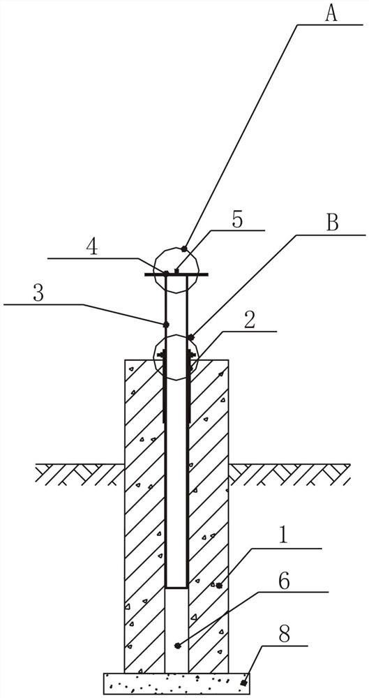
[0039] The embodiment of the present invention is a forced centering device that can be freely lifted, recycled and integrated. The forced centering device is suitable for all foundation pit projects, especially for foundation pits with large areas and irregular shapes (pit in pit, The foundation pit project of continuous pit) has better economic benefits. In addition, the forced centering device can also be better applied to foundation pit monitoring.

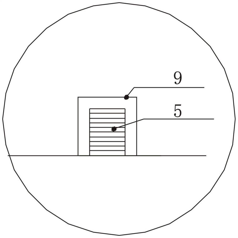
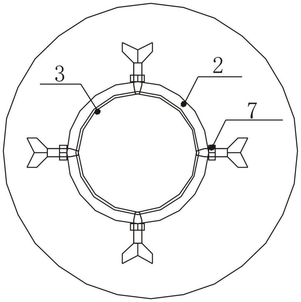
[0040] Such as Figure 1-4 As shown, the forced centering device includes a concrete pier 1 , a steel casing 2 , a steel pipe column 3 , an instrument erection platform 4 and a centering screw 5 .

[0041] specific,

[0042] Such as figure 1 As shown, two-thirds of the concrete pier 1 is buried underground, and the center of the concrete pier 1 is provided with a circular lifting channel 6 along its axial direction, and the steel casing 2 is embedded in the top opening of the circular lifting channel 6. The steel pipe colum...


PUM


Abstract

The invention discloses a forced centering device capable of being freely lifted, recycled and capable of achieving integrated operation. The forced centering device comprises a concrete pier, a steelsleeve, a steel pipe column, an instrument erecting platform and centering screws. The lower portion of the concrete pier is buried underground, a circular lifting channel is formed in the center ofthe concrete pier in the axial direction of the concrete pier, the steel sleeve is embedded from a top opening of the circular lifting channel, and the steel pipe column is matched with the steel sleeve in inner diameter and can extend into the steel sleeve and the circular lifting channel to slide up and down. A plurality of threaded holes are formed in the top of the steel sleeve in different directions of the circumferential face of the steel sleeve, and a nut matched with the corresponding threaded hole is screwed in each threaded hole. The instrument erecting platform is fixed to the topend of the steel pipe column, and centering screws are arranged on the top face of the instrument erecting platform. The device has the advantages of free lifting, recyclability, simple processing andmanufacturing (shaping manufacturing), high construction measurement precision, integrated operation, effective reduction of measurement personnel, remarkable improvement of measurement efficiency and the like.

Description

technical field [0001] The invention relates to the technical field of measuring instruments, more specifically, to a forced centering device capable of free lifting, recycling and integrated operation. Background technique [0002] With the accelerated pace of urban construction, a number of large-scale and super-large projects have emerged. Correspondingly, the area and depth of engineering foundation pits have increased significantly compared with the past. However, more and more special-shaped and irregular foundation pits, pit-in-pit or pit-connected-pit projects have made the construction period of the projects with heavy workload and high precision requirements more tense, and the measurement tasks are more arduous. Pit monitoring is more demanding and more difficult. [0003] Conventional measurement methods in this field include the tripod measurement method and the traditional forced centering device. Setting up the tripod measurement method is to set up the inst...

Claims


Application Information

Patent Timeline
IPC IPC(8): G01C15/08
CPCG01C15/08
Inventor 张全伟杨小军郑茂宇吴晓刚孙兴旺张文玉谷哓刘倩王婧
Owner CHINA CONSTR THIRD ENG BUREAU GRP CO LTD
Why Eureka
Try Eureka