Grating structure, optical waveguide and near-to-eye display system

An optical waveguide and grating technology, applied in the optical field, can solve the problems of low degree of freedom in design, few adjustable parameters, and poor diffraction efficiency of diffractive waveguides.

Pending Publication Date: 2020-10-23
SHENZHEN LOCHN OPTICS TECH CO LTD
View PDF3 Cites 3 Cited by
  • Summary
  • Abstract
  • Description
  • Claims
  • Application Information

AI Technical Summary

Problems solved by technology

[0003] At present, in the optical waveguide scheme using a two-dimensional diffraction grating, a cylindrical structure or a rhombus structure is generally used. The structure is very simple, with

Method used


Image

  • Grating structure, optical waveguide and near-to-eye display system
  • Grating structure, optical waveguide and near-to-eye display system
  • Grating structure, optical waveguide and near-to-eye display system

Examples


Embodiment 1

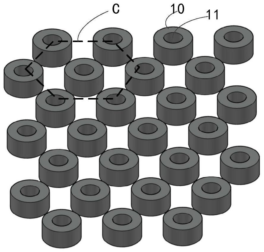
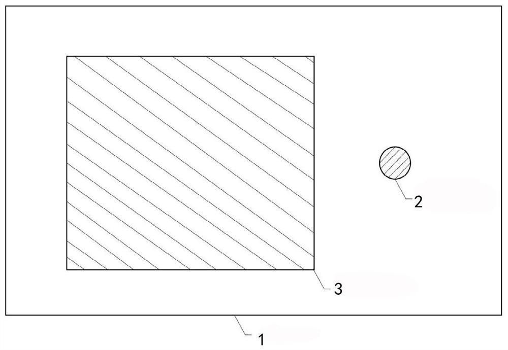
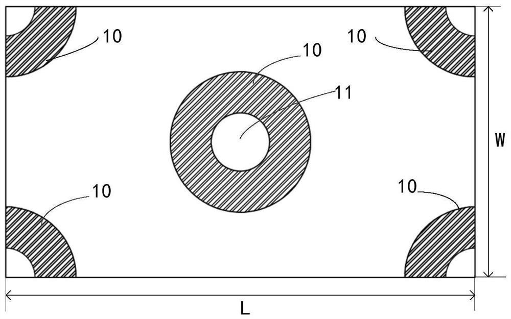
[0037] Embodiment 1: In this embodiment, the grating used in the optical waveguide is a hollow annular cylindrical grating, the inner diameter of each hollow annular cylindrical grating is 90nm, the outer diameter is 300nm, and the height is 100nm. period, see image 3 , a complete hollow annular cylindrical grating 10 is distributed in the middle, and a quarter of the hollow annular cylindrical grating 10 is distributed at the four corners. The long side dimension L of each grating period is 200nm-2μm, and the long side dimension L and the short side dimension The ratio of W is Also simulate the grating shown in this example, see figure 2 , arrange the grating periodically in the coupling-in region 2 and the coupling-out region 3 of the optical waveguide, so that the refractive index of the grating layer is 1.8, the forward order diffraction efficiency is 62.53%, the extended order diffraction efficiency is 8.35%, and The outcoupling order diffraction efficiency is 1.04%,...

Embodiment 2

[0038] Embodiment 2: In order to observe the change of the diffraction efficiency of the hollow annular cylindrical grating with different inner diameters, please refer to Figure 4 , we also provide a graph of the relationship between the inner radius of the grating structure and the diffraction efficiency. In this embodiment, the same grating structure as that shown in Embodiment 1 is that the outer diameter of each hollow annular cylindrical grating is 300nm and the height is 100nm, and in each grating period, please refer to image 3 , a complete hollow annular cylindrical grating 10 is distributed in the middle, and a quarter of the hollow annular cylindrical grating 10 is distributed at the four corners. The long side dimension L of each grating period is 200nm-2μm, and the long side dimension L and the short side dimension The ratio of W is The difference from the grating structure shown in Embodiment 1 is that in this embodiment, different optimizations are made to t...


PUM

PropertyMeasurementUnit
Heightaaaaaaaaaa
Thicknessaaaaaaaaaa
Inner diameteraaaaaaaaaa

Abstract

The embodiment of the invention relates to the technical field of optics, and particularly relates to a grating structure, an optical waveguide and a near-to-eye display system. The embodiment of theinvention provides the grating structure which is applied to the optical waveguide and the near-to-eye display system. The grating structure comprises a grating body. A through hole is formed in the grating body, and compared with a cylindrical structure grating and a rhombus structure grating, the grating structure is more in adjustable parameters, high in design freedom degree and easy to adjustdiffraction efficiency of the grating so that the grating structure provided by the embodiment of the invention is better in diffraction efficiency.

Description

technical field [0001] The embodiments of the present invention relate to the field of optical technology, and in particular to a grating structure, an optical waveguide, and a near-eye display system. Background technique [0002] Augmented reality is a technology that integrates virtual information with the real world. The design of the near-eye display system is a key link in augmented reality technology. For small-sized augmented reality glasses with better portability, the main solutions on the market are The optical waveguide is used as the transmission medium of light, and the optical waveguide is divided into geometric array waveguide, diffraction grating waveguide and volume holographic waveguide. Among them, the diffraction grating waveguide is convenient for nanoimprinting processing and the high degree of freedom of diffraction grating design, the more It has been paid more and more attention, and the diffraction grating acts like a thin film in the arrayed waveg...

Claims


Application Information

Patent Timeline
IPC IPC(8): G02B5/18G02B6/10G02B27/01
CPCG02B5/1842G02B5/1866G02B5/1814G02B5/1819G02B6/10G02B27/0101
Inventor 郭晓明宋强黄浩许恒深马国斌
Owner SHENZHEN LOCHN OPTICS TECH CO LTD
Why Eureka
Try Eureka