Supercharge Your Innovation With Domain-Expert AI Agents!

Capacitive touch key environment compensation circuit and method

A compensation circuit, capacitive technology, applied in electrical components, electronic switches, pulse technology, etc., can solve problems such as poor matching, large differences in channel parameters, and impact on response time.

Pending Publication Date: 2020-10-23
深圳市飞翼科技有限公司
View PDF0 Cites 2 Cited by
  • Summary
  • Abstract
  • Description
  • Claims
  • Application Information

AI Technical Summary

Problems solved by technology

Under some application conditions, the total capacitance difference between the long-wire button and the short-wire button is more than 5 times. After adjusting the reference capacitance to meet the Cp maximum button, the shortest button needs to be more than 25 times longer than it. In this way, in multi-button applications In the process of processing, it greatly affects the overall response time and becomes an insurmountable problem
[0012] To sum up, in the widely used multi-channel charge transfer key detection circuit at present, there are common defects that the parameters of each channel are greatly different and the matching is not good. 1. The impact of environmental parasitic capacitance on the touch key detection range, accuracy, and speed, which is used to achieve more convenient applications

Method used


Image

  • Capacitive touch key environment compensation circuit and method
  • Capacitive touch key environment compensation circuit and method
  • Capacitive touch key environment compensation circuit and method

Examples


Embodiment Construction

[0034] The technical solutions in the embodiments of the present invention will be clearly and completely described below with reference to the accompanying drawings in the embodiments of the present invention. Obviously, the described embodiments are only a part of the embodiments of the present invention, but not all of the embodiments.

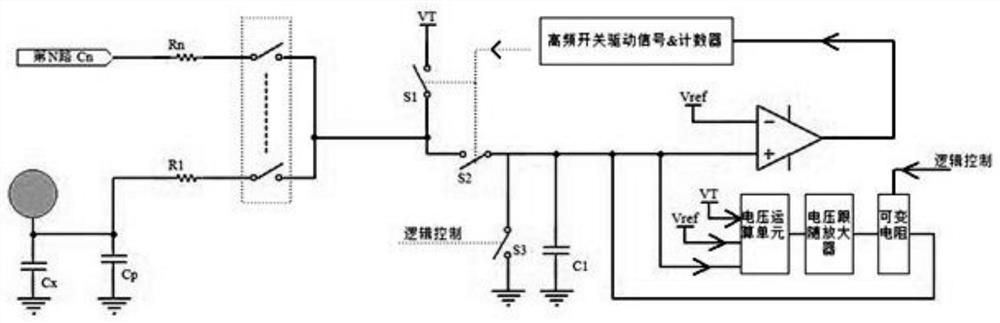
[0035] refer to Figure 3-4, A capacitive touch key environment compensation circuit and method, the circuit includes a detection unit, a voltage operation unit, a voltage follower amplifier, a variable resistance unit and a logic control unit, the detection unit includes a switch S1, a switch S2, a switch S3, a reference Capacitor C1, charging voltage source VT and comparator / AD converter, the voltage follower amplifier is a voltage follower amplifier, the variable resistance unit is a variable resistance, and the capacitance on the touch channel is composed of touch capacitance Cx and stray capacitance Cp; voltage operation The function o...


PUM


Abstract

The invention discloses a capacitive touch key environment compensation circuit and method. The circuit comprises a switch S1, a switch S2, a switch S3, a reference capacitor C1, a charging voltage source VT, a comparator / AD converter, a voltage operation unit, a voltage follower amplifier, a variable resistor unit and a logic control unit, and capacitors on a touch channel are composed of a touchcapacitor Cx and a stray capacitor Cp. The compensation method comprises the following steps: before start, the reference capacitor performs initial discharge, a detected capacitor is switched between a charging voltage source and the reference capacitor by using a high-frequency selector switch; charges charged by a charge transfer method are transferred to the reference capacitor; correspondingnegative voltage is obtained by calculating signals of reference capacitor voltage, the charging voltage source and reference voltage, and driving capability amplification is carried out. Charge discharge is performed on the reference capacitor through the variable resistor and the discharged charge is just equal to the charge charged by the stray capacitor in the period, so that the reference capacitor only maintains the charges charged by the touch capacitor; when the comparator or the AD converter judges that the voltage of the reference capacitor reaches the target reference voltage, thecomparison or the AD converter stops, and the size of the touch capacitor is judged according to the number of times of switching or time of the high-frequency switch.

Description

technical field [0001] The present invention relates to a non-capacitive touch key circuit, and more particularly, to a capacitive touch key environment compensation circuit and method. Background technique [0002] Capacitive touch button is a commonly used non-contact button. Compared with traditional mechanical buttons, it has the advantages of waterproof, long life, beautiful appearance and simple structure. It is widely used in operation panels of various electronic products. The basic principle of its realization is to set a certain area of ​​touch-sensitive disk in the product, which forms an inherent capacitance Cx with the product shell and the circuit board, and the general size is about 5P. When the user's finger is close to it, a certain capacitance (about 0.2P-1P) will also be formed, which will be superimposed on the original Cx to increase Cx. The capacitive button detection circuit is used to detect such a small amount of capacitance change, so as to realize...

Claims


Application Information

Patent Timeline
Patent Type & Authority Applications(China)
IPC IPC(8): H03K17/96
CPCH03K17/962
Inventor 张善辉
Owner 深圳市飞翼科技有限公司
Features
  • R&D
  • Intellectual Property
  • Life Sciences
  • Materials
  • Tech Scout
  • Unparalleled Data Quality
  • Higher Quality Content
  • 60% Fewer Hallucinations
Learn More