Humidity control unit and method

An air chamber, ambient air technology, used in heating methods, lighting and heating equipment, space heating and ventilation, etc.

Inactive Publication Date: 2020-10-23
MANTERS CORP
View PDF20 Cites 2 Cited by
  • Summary
  • Abstract
  • Description
  • Claims
  • Application Information

AI Technical Summary

Problems solved by technology

[0006] However, such systems have airflow flow limitations based on the size of the desiccant wheel used

Method used


Image

  • Humidity control unit and method
  • Humidity control unit and method
  • Humidity control unit and method

Examples


Embodiment Construction

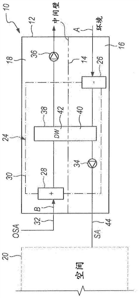
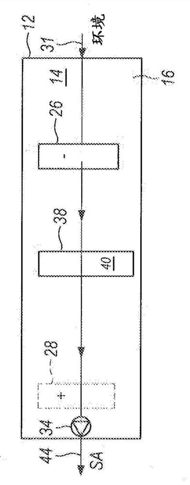
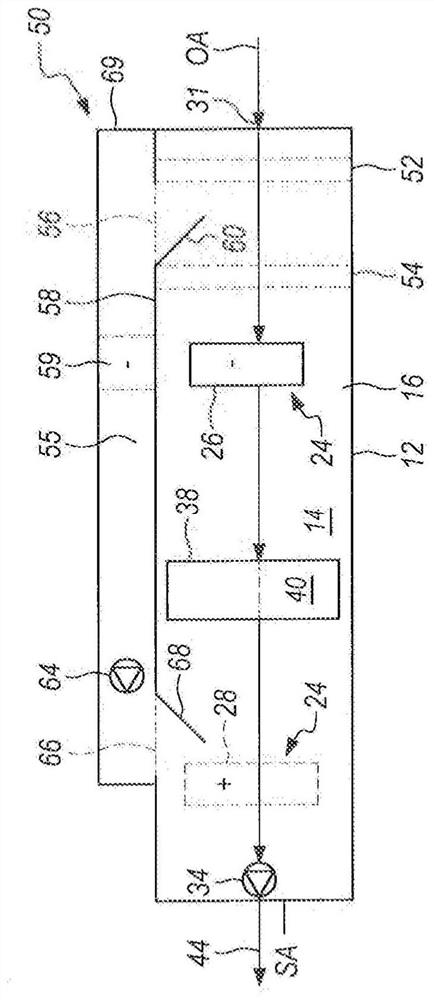
[0026] Referring now to the drawings in detail, and initially to FIGS. 1 and 2, there is shown a prior art air conditioning unit 10, generally of the type disclosed in US Patent Nos. 6,557,365, 6,711,907 and 7,047,751. The unit 10 includes an air chamber 12 having a dividing wall 14 generally centrally located in the air chamber and dividing the air chamber into separate air chambers, namely a first air chamber 16 and a second air chamber 18 . The unit is intended to use substantially only external ambient air in order to supply conditioned dehumidified air to the enclosure or space 20 under suitable or desired temperature and humidity conditions.

[0027] The prior art air conditioning unit of FIG. 1 also includes an associated direct liquid vapor compression expansion refrigeration system (DX) 24, which includes an evaporator or cooling coil 26 and a condenser coil 28, and not shown. The conventional compressor and expansion valve are connected by a liquid vapor pipeline 30 ...


PUM


Abstract

In a method and apparatus for conditioning air for an enclosure, a first ambient air stream is cooled by the cooling coil of a refrigerant cooling system to reduce its temperature and humidity content. The thus cooled and dehumidified air is then passed through a segment of a rotating desiccant wheel to reduce moisture content and increase temperature and is then supplied to the enclosure. The desiccant wheel is regenerated by the use of a second ambient air stream which is first heated with the condenser coil of the refrigerant system and then passed through the regeneration segment of the desiccant wheel. A bypass plenum is provided in the apparatus that selectively allows a third ambient air stream to be cooled in the plenum independent of the evaporator coil and desiccant wheel in thefirst plenum. That air stream is then supplied with the air treated in the first plenum to the enclosure.

Description

technical field [0001] The present invention relates to an air conditioning and dehumidification apparatus and method, and more particularly, to an air conditioning method and apparatus that uses desiccant wheel technology to control humidity while providing increased air flow rates. Background technique [0002] It is well known that conventional air conditioning designs are not well adapted to handle both the humidity and temperature loads of building spaces. Often, the main source of humidity load in a building space comes from the need to supply the space with outside make-up air, as this air usually has a higher moisture content than is required in the building. In conventional air conditioning systems, the cooling capacity of the air conditioning unit is therefore sized to accommodate both latent (humidity) and sensible (temperature) conditions at peak temperature design conditions. Proper dehumidification capacity is achieved when there is sufficient cooling demand. ...

Claims


Application Information

Patent Timeline
Patent Type & Authority Applications(China)
IPC IPC(8): F24F3/044F24F3/048F24F3/052F24F3/14F24F3/147F24F3/153
CPCF24F3/1423F24F2003/1464F24F2003/1446F24F3/1405F24F3/147F24F2003/144F24F3/1429
Inventor M·布彻P·丁纳格R·纽瓦德
Owner MANTERS CORP
Why Eureka
Try Eureka